
Unijunction Transistor Tutorials
The unijunction transistor (UJT) operates based on its unique structure, allowing it to function effectively as a relaxation oscillator. The device features a single P-N junction that creates a characteristic negative resistance region, making it suitable for generating oscillatory waveforms. The operation begins with the application of a voltage to the emitter, which is critical for the triggering of the device.
In practical applications, the capacitor C is charged through the resistor R1 at a rate determined by the RC time constant. The value of R1 and the capacitance of C directly influence the frequency of oscillation. As the voltage across C rises, the emitter voltage eventually reaches the threshold of 0.6 volts, causing the UJT to switch from a high-resistance state to a low-resistance state. This transition allows the capacitor to discharge rapidly, creating a sharp pulse of voltage.
The output pulse generated across R3 can be utilized for various applications, including triggering other circuits or providing timing signals. The sawtooth waveform produced across C can be further processed or filtered depending on the specific requirements of the application. The simplicity and effectiveness of the UJT in generating oscillations make it a valuable component in electronic circuits where timing and waveform generation are essential.
In summary, the unijunction transistor serves as a versatile component in electronic design, enabling the creation of oscillatory signals through its unique characteristics and operational principles.The unijunction transistor (UJT) is made of a bar of N type material with a P type junction (the emitter) near the centre. Base 1 is connected to zero volts and base 2 to the positive supply. The resistance between the two bases (the INTERBASE RESISTANCE) is typically 10k. With the emitter unconnected, the bar acts as a potential divider, and abou t 0. 5 volts appears at the emitter. If a voltage is connected to the emitter, as long as it is less than 0. 5 volts, nothing happens, as the P-N junction is reversed biased. (see the right hand diagram). When the emitter voltage exceeds 0. 5 volts, the junction is forward biased and emitter current will flow. This increase in current is equal to a reduction of resistance between base 1 and the emitter. In the circuit, C charges via R1. When the voltage across C exceeds 0. 6 volts, the b1/emitter junction goes low resistance and discharges C. The result is a sawtooth waveform across C. There is also a pulse of current through R3, giving a pulse of voltage across it. This circuit is called a relaxation oscillator. The voltage across C charges up slowly then suddenly relaxes. 🔗 External reference
Related Circuits
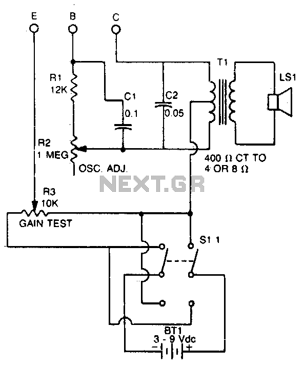
This tester checks the polarity of transistors (PNP or NPN). An audible signal indicates the gain. Additionally, the tester can function as a GO/NO GO tester for matching unmarked devices. The transistor tester is designed to evaluate the polarity and...
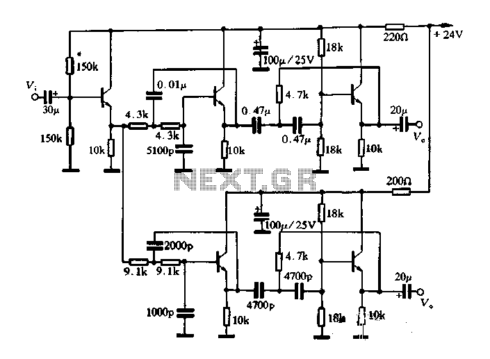
This article describes a band-pass filter circuit diagram utilizing transistors. A band-pass filter is an essential electronic circuit that allows signals within a certain frequency range to pass while attenuating frequencies outside that range. The circuit typically consists of a...
Following the development of the original 4-pin OM802 timer IC by SIGNETICS ITT - GEMINI in 1969/1970, a new and innovative integrated circuit known as the NE-555 timer IC was introduced to the market in May 1971 by Signetics...
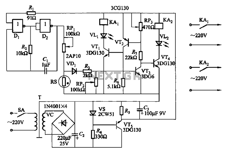
Two NAND gates (Di, Dz) and a resistor (Rz) along with capacitors (C1, etc.) form an RC self-excited multivibrator with an oscillation frequency of 2.5 Hz and an oscillation amplitude of 4 V. This circuit is used as a...
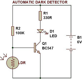
An automatic dark detector senses darkness. As the light level decreases and the light-dependent resistor (LDR) reaches the maximum threshold resistance, the circuit automatically activates the LED D1. Conversely, a light detector senses light, and when the light level...
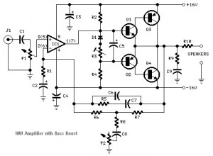
This audio amplifier circuit is based on the operational amplifier NE5532 and utilizes a pair of power transistors, TIP41A and TIP42A. It is capable of delivering up to 10W of audio power output into an 8-ohm speaker. The design...