
Universal motor control with built in self timer

The universal motor control circuit described operates by regulating the power supplied to a commutator motor, allowing for precise control over the motor's speed and operation time. It incorporates a self-timer feature, which automatically disconnects the motor after a predetermined period, thus preventing overheating or damage due to prolonged operation.
The circuit typically includes a silicon-controlled rectifier (SCR) configuration, with SCR1 and SCR2 managing the power flow to the motor. SCR1 is responsible for the initial control, while SCR2 can be upgraded to a higher-rated component, such as the C30B SCR, to accommodate motors under heavy loads. This enhancement is critical for ensuring the reliability and longevity of the circuit when dealing with high current demands.
The timing mechanism is achieved through the use of capacitor C1, which, when adjusted, alters the time delay before the motor is turned off. Increasing the capacitance of C1 will extend the delay period, allowing for longer operational times before automatic shutdown occurs. This feature is particularly useful in applications where the motor must run for a specific duration without manual intervention.
Overall, this circuit provides a robust solution for controlling universal motors, with the flexibility to adapt to various operational requirements through component selection and configuration adjustments.Universal motor control with built-in self-timer. Use this circuit only with motors having commutators. If heavy motor loads are anticipated, use a larger-rated C30B SCR in place of the GE-X1 for SCR2. To increase the time delay increase the capacitance of 01 (courtesy General Electric Company). 🔗 External reference
Related Circuits
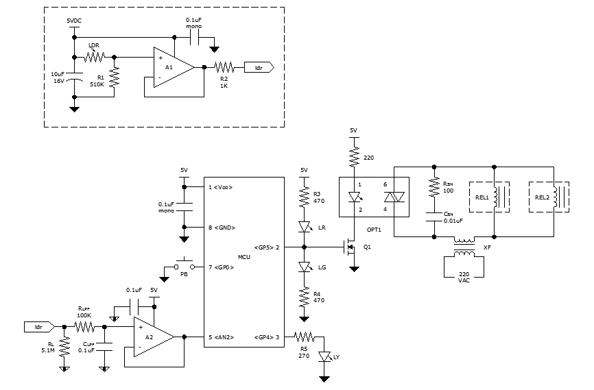
While discussing an all-linear automatic night light circuit, it was mentioned that an MCU-based Automatic Night Light Controller (ANLC) was being tested. The firmware has been tweaked since then. Recently, the sensor was installed outdoors and connected to control...
The purpose of this circuit is to power a lamp or other appliance for a specified duration (30 minutes in this case) and then automatically turn it off. This functionality is particularly useful for reading in bed at night,...
This document serves as a compilation of design notes, providing practical details as construction progresses, along with some photographs that will be included in due course. Currently, it functions as a progress report, blending immediate plans with actual construction,...
The circuit utilizes two white LEDs, with the second LED connected across the emitter of the transistor and the negative ground. It requires its own limiting resistor in series, similar to R15 and D3 in the circuit diagram. If...
A very simple circuit that will find application in the case where you have a lot of telephones installed on a telephone line and would want to know if somebody of them is open. Thus, you will not be...
It is a miniature 10/100-MbBit Ethernet module that includes an integrated microcontroller. The price is less than $60. With its minimal dimensions of 1.38 in. x 2.16 in. (34.5 mm x 54 mm), the communications module can be used...