
USB Performance Monitor
The USB Performance Monitor effectively combines analog metering with digital control, providing a visually engaging way to monitor computer performance in real-time. The use of the PIC18F2550 microcontroller ensures efficient processing and communication capabilities over USB, while the PWM control of the RGB LED allows for dynamic visual feedback based on system activity. The incorporation of potentiometers for calibration enhances versatility, accommodating various VU meters and ensuring accurate readings. The design prioritizes compactness and user-friendliness, featuring a straightforward assembly process and accessible programming interfaces. Overall, this project exemplifies an innovative approach to integrating traditional analog components with modern digital technology, resulting in a practical tool for performance monitoring in computing environments.The USB Performance monitor is a PIC18F2550 based device which shows the performance of your computer using two analogue meters and a RGB LED. The design is based around a stock Hi-Fi VU-meter which is controlled using PWM from the PIC18F microcontroller.
This project was inspired by a friend of mine who wanted a way to move his computer`s HDD LED onto the desktop. After toying around with sending Windows performance counters over USB via the Generic HID protocol I came up with the idea of using a VU meter I had lying around to build a full USB Performance Monitor. Even the HDD LED itself is `improved` in this project. Instead of a single-colour flashing LED this project uses a RGB LED which varies its intensity based on the level of utilisation and its colour based on reading, writing or both.
Lastly a single hardware button was added to allow you to quickly enable and disable the device without having to grab the mouse. The PIC18F2550 firmware is written in Hi-Tech C and the Windows host software is written in C# using my Open Source Framework for USB Generic HID devices based on the PIC18F and Windows.
As always, the software is GPL open source and can be downloaded from the section at the end of this article. The hardware is based around the PIC18F2550 microcontroller which has on-board USB. A minimal component count was used to connect the device to the USB port as well as to the switch, meters and RGB LED.
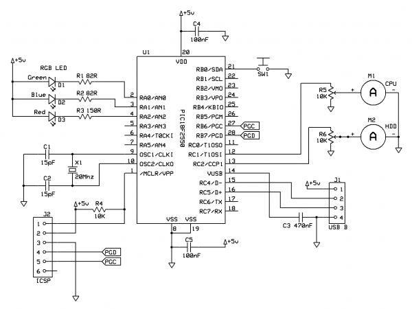
The overall circuit schematic can be seen in the following diagram: Two potentiometers are included in the design to allow quick calibration of the full-deflection power required by the VU-meter (as this can vary from meter to meter). Other than that the design is fairly straight-forward; the RGB LED resistors were chosen according to the data-sheet to allow the highest brightness from the LED since we will be controlling the output using PWM.
The PIC is clocked at 20Mhz to allow the full 48Mhz PLL speed to be used, this is useful since PWM control of the LED requires as much processor speed as possible. In order to fit the device in the smallest possible space I designed a single-sided PCB. However, the design is simple enough to be easily built on a piece of strip-board if you don`t have PCB etching equipment.
Here is a picture of the PCB design: Note that the USB connector is facing downwards, this is to allow the connection to be plugged in inside of the case allowing the cable to be routed out the back of the device. This allows you to change the USB cable if required for a longer or shorter cable, however you could directly solder the cable to the PCB or use a different type of internal connection.
All of the connected devices connect using Molex style connectors to allow the device to be easily assembled and dissembled. I`ve also include a header for the PICkit 2 programmer to make it easier to develop the firmware by programming the PIC in-circuit.
The RGB LED I used was a clear-lens LED, this meant that the colour mixing was difficult to see close-up and also the LED was very intense. To cure this I diffused the LED lens by buffing it using a Dremel until the lens was milky-white. If you don`t have a Dremel you can do the same trick by simply rubbing the lens with fine sandpaper. To re-purpose the VU meter I took the front plastic off the meter and used a sharp knife to cut down behind the existing panel marker.
Be very careful when doing this; always cut down and away from yourself! You need to be careful not to push the panel marker up into the needles or you will bend them. Once the panel marker was removed I placed it in my scanner and scanned an image of it into Photoshop (this is a good trick since it preserves the scale of the original). I then used Photoshop to replace the logarithmic VU markings with a linear percentage scale (more about the logarithmic vs linear scales later!).
Once I had my desired design I simply printed it out onto th 🔗 External reference
Related Circuits
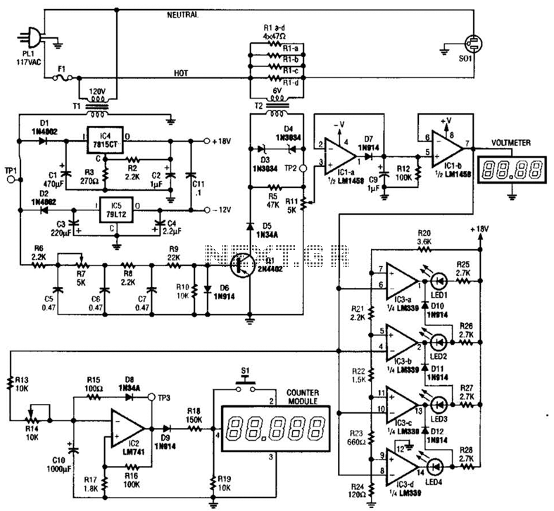
The ECM circuit comprises four sections, as illustrated in the block diagram. A power converter generates a voltage that correlates with the actual real power consumed by the load. This voltage supplies both a bar graph and a voltage-to-pulse...
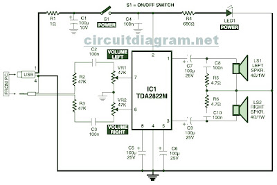
This is the circuit diagram of a USB-powered computer speaker, commonly referred to as multimedia speakers for PCs. The circuit features a single-chip design, operates on a low-voltage electrical power supply, is compatible with USB power from computers, includes...
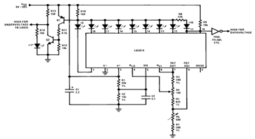
By utilizing several resistors, LEDs, and the LM3914 bar/dot display driver IC, it is possible to create a straightforward 5V voltmeter monitor circuit. This circuit offers TTL-compatible undervoltage and overvoltage warning signals. A complete circuit schematic is available below. The...
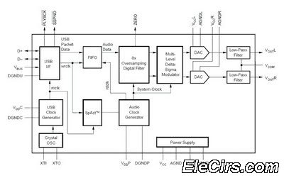
The USB sound card circuit utilizes the PCM2702 integrated circuit (IC) to create a fully functional USB sound card. The design is straightforward, allowing for the easy implementation of audio processing capabilities. The PCM2702 is a versatile USB audio controller...
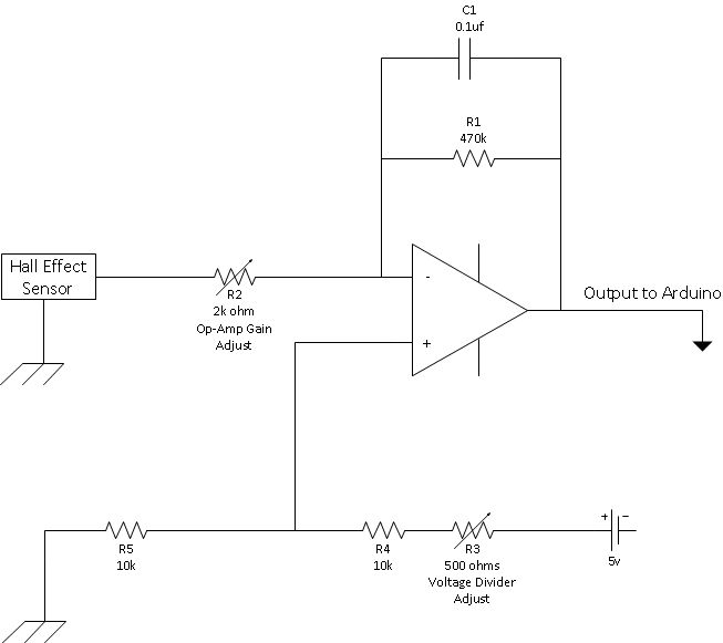
This is a straightforward schematic of an amplifier and filter. The circuit primarily features an LM124 operational amplifier configured in an inverting setup. The schematic illustrates a basic audio amplifier and filter circuit utilizing the LM124 operational amplifier. The LM124...
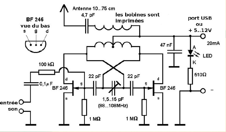
This compact FM transmitter is designed for connection to a USB port and has a range of approximately 50 meters. It can be utilized alongside multiple mini-transmitters to create a diverse and engaging radio program. The power supply through...