
Video Wire: Enable Video Transmission Via Long Cables
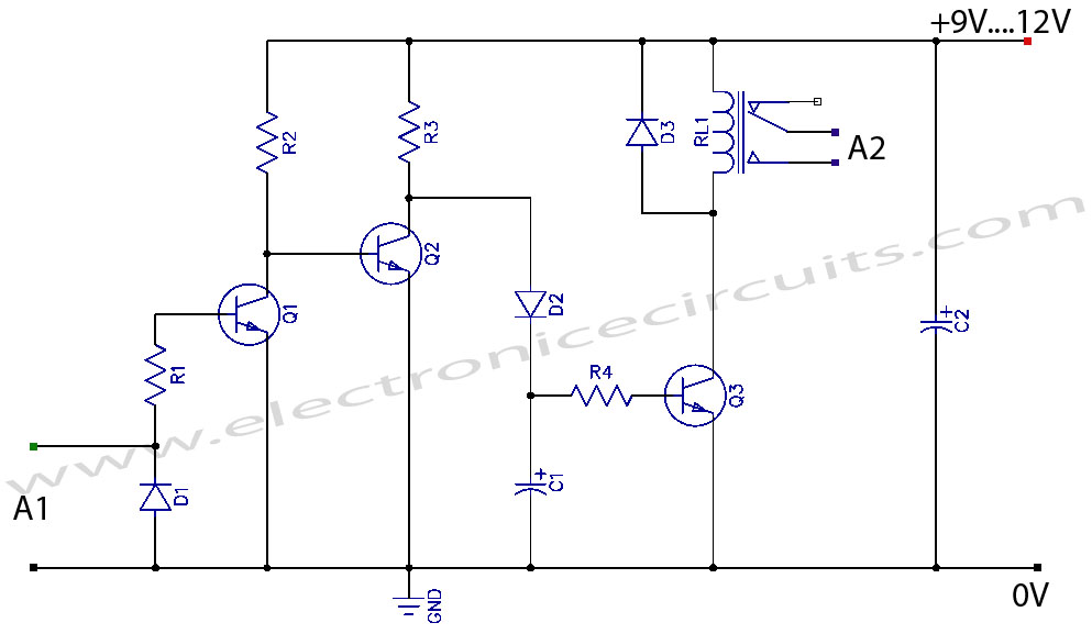
The circuit described is designed to facilitate the transmission of video signals over extended distances, which is essential in applications where camera placement is far removed from the monitoring or recording equipment. The primary component of this system is the video amplifier, which serves to boost the strength of the video signal, ensuring that it maintains integrity and quality despite the signal degradation that can occur over long wire runs.
At the sender end of the circuit, the video amplifier takes the weak video signal output from the camera. This signal is typically low in amplitude, making it susceptible to noise and interference when transmitted over long distances. The amplifier enhances the signal's amplitude, allowing it to travel through the wire without significant loss of quality.
The circuit may include additional components such as capacitors to filter out noise and resistors to set the gain of the amplifier. The choice of wire is also critical; shielded cables are often recommended to minimize electromagnetic interference, which can distort the video signal during transmission.
On the receiving end, a complementary video amplifier may be employed to further process the signal and restore it to a usable level for display or recording. The design should also consider impedance matching to prevent reflections and signal loss at the connection points.
Overall, this circuit design is crucial for applications in surveillance, broadcasting, and any scenario where high-quality video transmission is required over long distances.This circuit enables you to connect your camera with very long wire. The circuit is actually a video amplifiers. At the sender part, the amplifier is used to. 🔗 External reference
Related Circuits
Although there is a need for an integrated circuit (IC), the interface between the modulator and audio-video signals has not yet been developed as an IC. This is primarily due to the complexity of such a design, the variations...
This is an SCR timer circuit. In this circuit, an SCR is utilized to activate the final actuator, which is a buzzer. The time constant of the circuit is determined by resistor R1 and capacitor C1. The buzzer will...
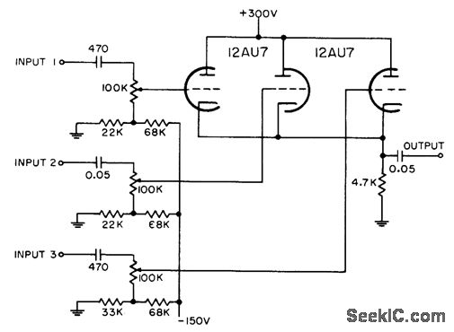
Each grid is biased to cutoff, allowing the mixer to accept only positive-polarity pulses with sufficient amplitude to overcome this bias. -NBS, "Handbook Preferred Circuits Navy Aeronautical Electronic Equipment," Vol. 1, Electron Tube Circuits, 1963, p N4-2. In a typical...
The video amplifier illustrated in the diagram represents a well-established design that is simple yet highly effective. However, there is a risk of damaging the transistors if the potentiometers, which control black level and signal amplitude, are set to...

The power output of most of these circuits is very low because no power amplifier stages were incorporated. The transmitter circuit described here includes an additional RF power amplifier stage, following the oscillator stage, to increase the power output...
VCR Camera Video Detector Switch Controller Circuit. This video detector switch controller circuit utilizes the video output from a VCR or camera to... This circuit functions as a video detector switch controller, designed to manage the video output from a...