
Video modulator circuit

The TDA6800 is a versatile integrated circuit specifically designed for modulating video signals onto VHF and UHF carriers. This modulator circuit is suitable for applications in television broadcasting, video transmission, and other related fields.
The circuit operates at a nominal power supply of 5 V, which is essential for the proper functioning of the IC and the modulation process. In negative modulation mode, the circuit requires a minimal number of external components, which typically include resistors and capacitors for filtering and stabilization. This simplicity allows for easy integration into various systems.
For positive modulation, an external clamp circuit is required to ensure that the video signal is properly biased for modulation. This clamp circuit can be implemented using a diode and a capacitor, which helps to maintain the signal level within the desired range and avoid distortion during the modulation process.
The TDA6800 IC itself contains all necessary circuitry for generating the modulation signal and can provide high-quality output with minimal distortion. Its design allows for flexibility in modulation schemes, making it suitable for a wide range of video applications. Additionally, the IC supports general-purpose modulation without the need for extensive additional components, enhancing its utility in various electronic designs.
Overall, the TDA6800 modulator circuits are efficient and effective solutions for video signal modulation, providing a reliable method for transmitting video over VHF and UHF frequencies.These are modulator circuits for modulation of video signals on a VHF/UHF carrier. The circuits require a 5 V power supply and few external components for the negative modulation mode. For positive modulation an external clamp circuit is required. The circuits can be used as general-purpose modulators without additional external components. The IC is TDA6800.
Related Circuits
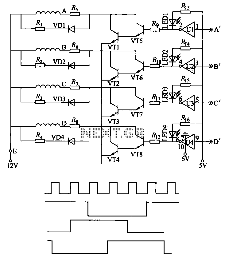
This machine utilizes the FD-CAS-923 1-stepper motor control experiment board with a 4-phase stepper motor to avoid its schematic shown in Figure 4-42a. The JK1 cop 40 core flat cable connector allows for signal arrangements compatible with EICE51 simulation...
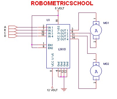
The electronic schematic of a DC motor driver using the L293D, as illustrated in Figure 2, enables the control of two DC motors continuously. It allows for one motor to rotate clockwise while the other rotates counterclockwise. Additionally, all...
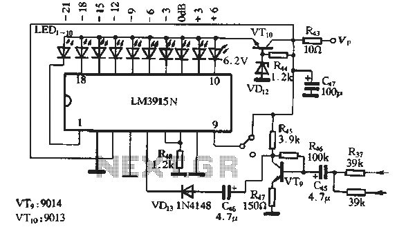
The circuit features a manual recording level control function. When in recording mode, the recording level is indicated by the LM3915N. The sound recording circuit, as illustrated in Figure 3-17, employs an RC network and an associated audio recording...
By adjusting the oscillators so their frequencies are very nearly the same, the difference between them is made audible as a beat note. This beat note changes slightly when the search loop is moved over or near to a...
This circuit is a gradual clear/fade switch for a two-wire connection, designed for simple installation. It activates the lights as needed by turning the switch dial upward. A positive supply of 2V is provided through resistor R. The capacitor...
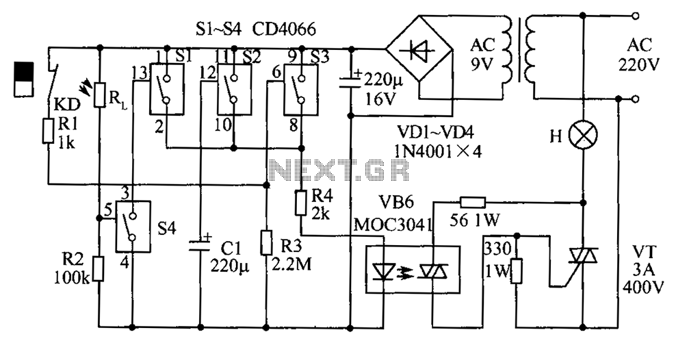
The circuit diagram illustrates a group of four analog electronic circuit switches (S1 to S4). Switches S1, S2, and S3 are utilized in a parallel delay circuit. When the power is activated, resistor R4 drives the triac VT, which...