
vu meter em84
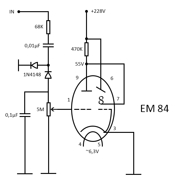
The Magic Eye indicator tubes, specifically the EM84, serve as a unique visual component in audio equipment, providing a captivating display that responds to audio levels. The EM84 operates by utilizing a phosphorescent screen that glows when a voltage is applied, creating a visual representation of the audio signal. In this application, the EM84 can be integrated into the amplifier circuit to function as a VU meter, allowing for real-time monitoring of audio output levels.
The incorporation of a triode amplifier stage is essential for driving the EM84, as it provides the necessary gain and ensures that the tube operates within its optimal range. The triode's characteristics, such as its high gain and linearity, make it a suitable choice for this application. The design should consider the input signal's characteristics to ensure compatibility with the triode's requirements.
In terms of circuit design, the preamp stage featuring the BC171 transistor can be designed to interface with the triode, allowing for a seamless transition between solid-state and tube amplification. While a MOSFET could provide higher input impedance, the use of a BC171 aligns with the objective of maintaining a tube-centric approach. The circuit should include biasing resistors for the triode, coupling capacitors to block DC while allowing AC signals to pass, and appropriate power supply considerations to ensure stable operation.
Overall, the integration of the EM84 as a VU meter within a tube amplifier circuit reflects a blend of vintage aesthetics and modern audio engineering, creating a visually appealing and functional component that enhances the user experience.From all the existing tubes, for sure the most interesting ones are the indicator tubes. From the 1930 ²s when they were invented, they captivated the eyes with the greenish shimmering light, thus the Magic Eye term appeared. The magic eye tubes are just small CRT derivations, usually they also have a triode built-in, as an amplifier.
I had two EM84 laying around for some time ( EM84 are cheap and easy to find, mostly on eBay ), and as I was planning to start an all tube stereo amplifier, it made perfect sense to use magic eye tubes as vu-meters, although EM84 can hardly be called a magic eye, it is more a magic stripe . I am also experimenting with a preamp stage with a BC171 transistor ( a MOSFET would be a better choice for high input impedance ), but I think that in order to keep it all tube I will try with a triode.
🔗 External reference
Related Circuits
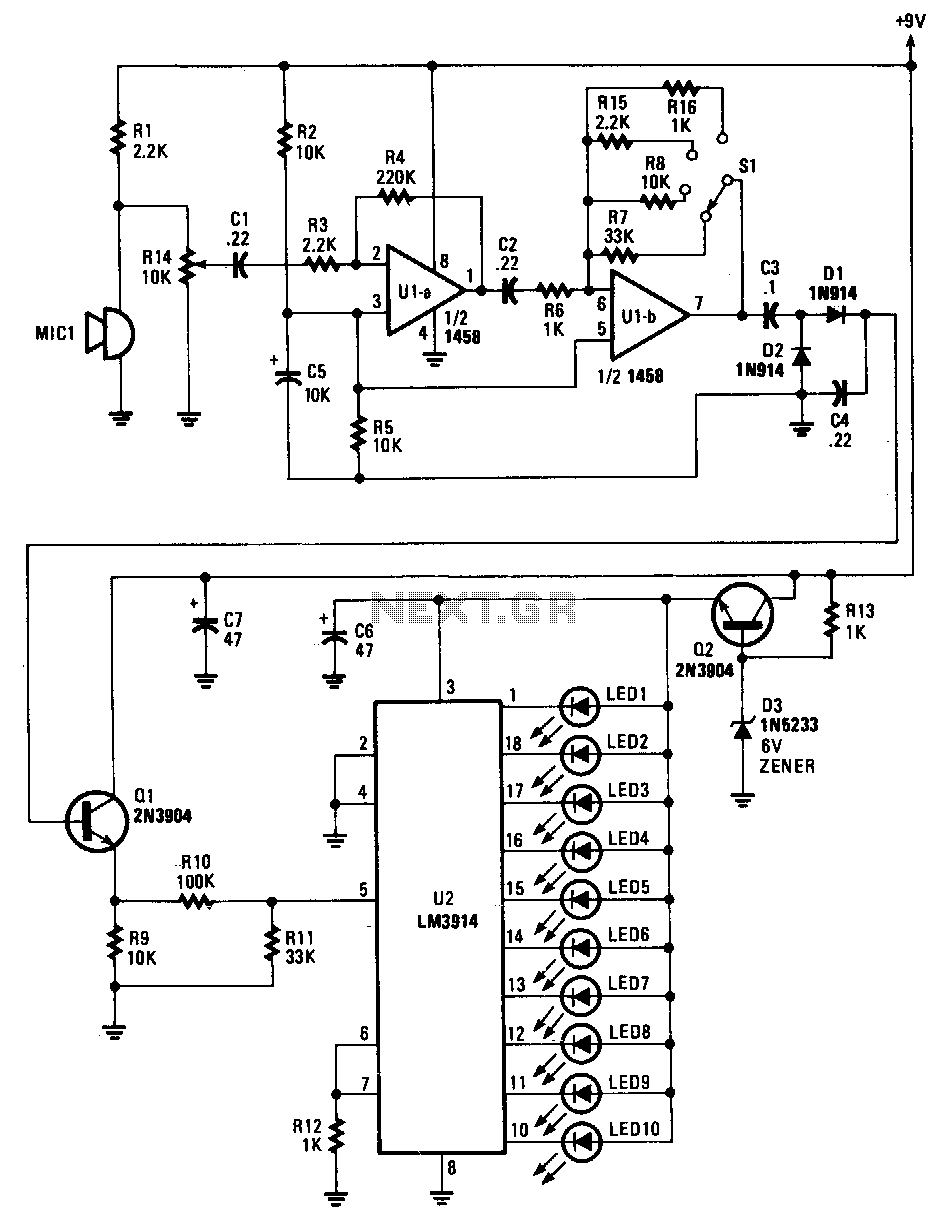
Sounds are captured by MIC1 and sent to the input of the first operational amplifier (op-amp). The signal is subsequently directed to the input of the second op-amp, U1B, where it is amplified by a factor ranging from 1...
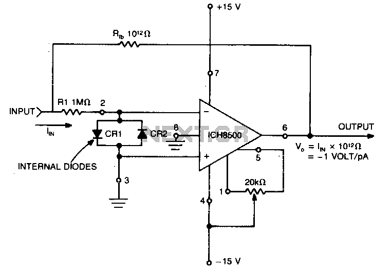
A highly sensitive picoammeter (−1 V/pA) utilizes an amplifier configured in the inverting or current summing mode. It is crucial to eliminate stray currents from entering the current summing mode. The circuit stabilizes to within 1% of its final...

This is a low-power voltmeter circuit designed for use with alternative energy systems operating on 12V and 24V batteries. The voltmeter features an expanded scale that displays small voltage increments within the 10 to 16V range for 12V batteries...
1 kHz is a commonly used test frequency, and I resolved to see if I could make an inductance meter that uses a 1 kHz test signal at a low level. I also wanted to use a low level...
The following circuit enables measurement of the inductance of the inductor labeled LX, which is the inductance to be measured. The output of the circuit is a TTL square wave whose frequency relates to the inductance being measured. The...
The circuit is connected in parallel with the output of a power amplifier and provides the signal level from the output. By adjusting the resistance R1 in the input circuit, the power indication can be adapted to the resistance...