Water level alarm
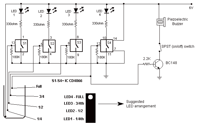
This circuit not only indicates the amount of water present in the overhead tank but also gives an alarm when the tank is full. The circuit uses the widely available CD4066, bilateral switch CMOS IC to indicate the water level through LEDs. When the water is empty the wires in the tank are open circuited and the 180K resistors pulls the switch low hence opening the switch and LEDs are OFF. As the water starts filling up, first the wire in the tank connected to S1 and the + supply are shorted by water. This closes the switch S1 and turns the LED1 ON. More: As the water continues to fill the tank, the LEDs2, 3 and 4 light up gradually. The no. of levels of indication can be increased to 8 if 2 CD4066 ICs are used in a similar fashion. When the water is full, the base of the transistor BC148 is pulled high by the water and this saturates the transistor, turning the buzzer ON. The SPST switch has to be opened to turn the buzzer OFF. Remember to turn the switch ON while pumping water otherwise the buzzer will not sound!
The circuit operates by utilizing a CD4066 bilateral switch, which allows for the control of multiple outputs based on the water level detected in the overhead tank. The circuit is designed to monitor the water level and provide visual feedback through a series of LEDs, as well as an auditory alarm when the tank reaches its full capacity.
Initially, when the tank is empty, the wires connected to the water level sensing points remain open-circuited. In this state, the 180K ohm resistor connected to the control pin of the CD4066 pulls the control voltage low, resulting in the switch being open and all LEDs remaining off. As water begins to fill the tank, the conductive properties of water bridge the connection between the sensing wire and the positive supply, effectively closing the switch (S1). This action activates the first LED (LED1), indicating that water has been detected at the lowest level.
As the water level continues to rise, additional sensing points can be implemented to activate subsequent LEDs (LED2, LED3, LED4) in a sequential manner. This gradual illumination provides a clear visual representation of the water level within the tank. The circuit can be expanded to indicate up to eight different levels by incorporating a second CD4066 IC, thus enhancing the monitoring capability.
When the tank reaches its full capacity, the water level rises sufficiently to pull the base of the BC148 transistor high. This saturation of the transistor allows current to flow through the buzzer, sounding an alarm to alert users that the tank is full. The alarm can be silenced by opening the single-pole single-throw (SPST) switch, which interrupts the circuit and stops the buzzer from sounding.
It is crucial to ensure that the SPST switch is activated while the water pump is operational; otherwise, the buzzer will not activate to signal the tank's fullness. This circuit thus offers a reliable method for monitoring water levels while providing both visual and auditory alerts, ensuring efficient management of water resources in overhead tanks.This circuit not only indicates the amount of water present in the overhead tank but also gives an alarm when the tank is full. The circuit uses the widely available CD4066, bilateral switch CMOS IC to indicate the water level through LEDs.
When the water is empty the wires in the tank are open circuited and the 180K resistors pulls the switch low hence opening the switch and LEDs are OFF. As the water starts filling up, first the wire in the tank connected to S1 and the + supply are shorted by water.
This closes the switch S1 and turns the LED1 ON. As the water continues to fill the tank, the LEDs2 , 3 and 4 light up gradually. The no. of levels of indication can be increased to 8 if 2 CD4066 ICs are used in a similar fashion. When the water is full, the base of the transistor BC148 is pulled high by the water and this saturates the transistor, turning the buzzer ON. The SPST switch has to be opened to turn the buzzer OFF. Remember to turn the switch ON while pumping water otherwise the buzzer will not sound! 🔗 External reference
Warning: include(partials/cookie-banner.php): Failed to open stream: Permission denied in /var/www/html/nextgr/view-circuit.php on line 713
Warning: include(): Failed opening 'partials/cookie-banner.php' for inclusion (include_path='.:/usr/share/php') in /var/www/html/nextgr/view-circuit.php on line 713
