
Waveforms of a monostable multivibrator (triggered)
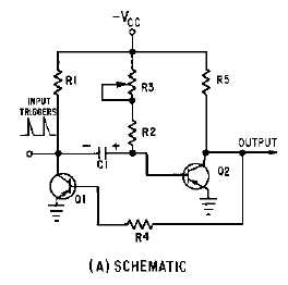
No description available.
Related Circuits
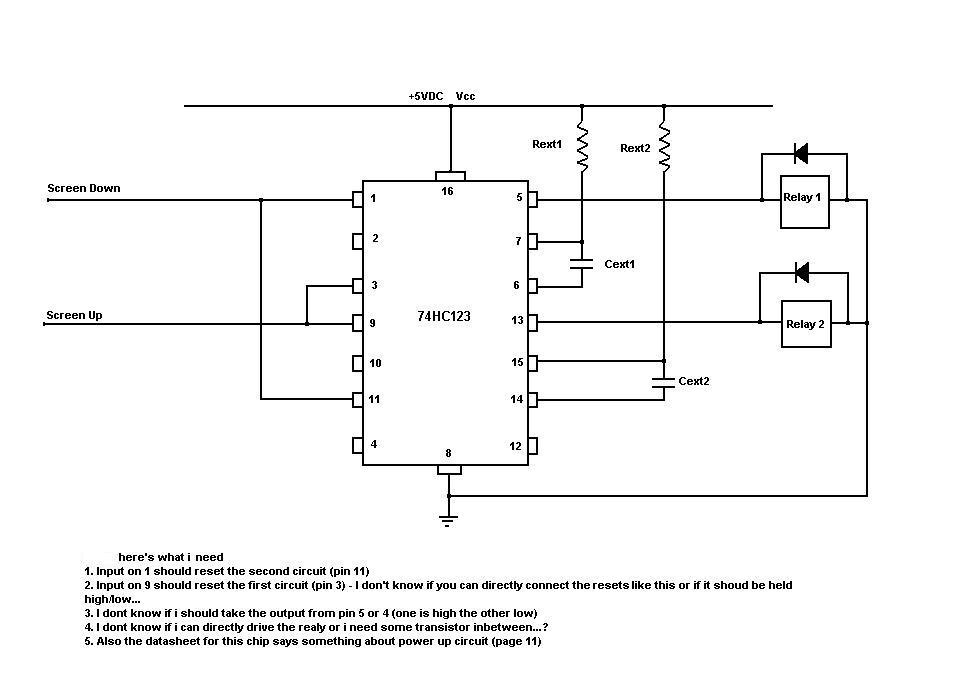
A monostable multivibrator is being designed to utilize the output of an infrared circuit to trigger a relay for a specified duration using a one-shot configuration. The monostable multivibrator, often implemented using a 555 timer IC in monostable mode, serves...
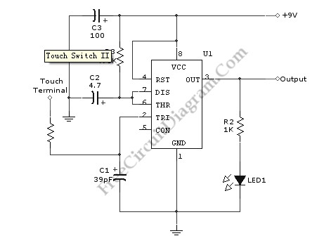
Utilizing the specified values depicted in the schematic diagram, this circuit features a timed ON period of 4 seconds. The ON time is governed by the values of capacitor C2 and resistor R3; increasing either C2 or R3 will...
The astable multivibrator presented in Wikipedia and college materials is depicted on the left side of the image. In contrast, the schematic on the right side is sourced from an LTSpice example. The right schematic is incorrectly drawn, and...
Electronics tutorial about the monostable multivibrator circuit, also known as a one-shot monostable multivibrator, used as a pulse generator circuit. The monostable multivibrator is a crucial component in electronic circuits, functioning as a pulse generator that produces a single output...
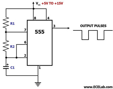
This circuit diagram illustrates the configuration of a 555 timer integrated circuit (IC) as an astable multivibrator. An astable multivibrator is a timing circuit characterized by unstable 'low' and 'high' states. Consequently, the output of an astable multivibrator continuously...
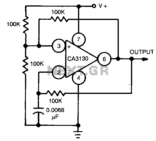
This circuit utilizes the CA3130 BiMOS operational amplifier, which operates at a frequency of 1 kHz. It features a rail-to-rail output swing, ensuring that the output can reach the supply voltage levels. The frequency of operation remains independent of...