
Wien bridge oscillator
For a linear circuit to oscillate, it must satisfy the Barkhausen conditions: its loop gain must equal one, and the phase around the loop must be an integer multiple of 360 degrees. Linear oscillator theory does not address the startup process or how amplitude is determined. The linear oscillator can theoretically support any amplitude. In practice, the loop gain initially exceeds unity. Random noise exists in all circuits, some of which is near the desired frequency. A loop gain greater than one allows the amplitude of the frequency to increase exponentially with each loop. With a loop gain above one, the oscillator will start. Ideally, the loop gain should be slightly greater than one; however, it is often significantly higher in practice. A higher loop gain accelerates the startup process and compensates for gain variations due to temperature and the desired frequency in tunable oscillators. For the oscillator to initiate, the loop gain must remain above one under all conditions.
However, a loop gain exceeding one poses a disadvantage. Theoretically, the oscillator's amplitude could increase indefinitely, but in practice, it will rise until it encounters limiting factors such as power supply voltage or output current limits, leading to gain compression. In a stable oscillator, the average loop gain equals one. While limiting stabilizes output voltage, it introduces harmonic distortion and affects frequency stability. The distortion level correlates with the extra loop gain utilized for startup. High extra loop gain at small amplitudes necessitates a larger reduction at higher instantaneous amplitudes, resulting in increased distortion. Distortion is also related to the final oscillation amplitude. Although an amplifier's gain is ideally linear, it is often nonlinear in practice. This nonlinearity can be represented as a Taylor series, where higher-order terms have minimal effects at small amplitudes but become pronounced at larger amplitudes. Therefore, to minimize distortion, the oscillator's output amplitude should remain a small fraction of the amplifier's dynamic range.
Rather than using limiting to maintain an average gain of one around the loop, Meacham proposed a circuit that establishes the loop gain at one while the amplifier operates within its linear region. This design reduces distortion and enhances frequency stability. Meacham's quartz crystal oscillator, based on a Wheatstone bridge, marked a significant advancement over previous designs. At the oscillator frequency, Meacham's configuration was a linear circuit with constant gain, eliminating distortion.
The Wien bridge oscillator circuit typically features a configuration that includes two resistors and two capacitors arranged in a bridge format. The resistors R1 and R2 are part of the feedback network, while the capacitors C1 and C2 help determine the frequency of oscillation. The self-regulating feature of the incandescent lamp Rb serves as a variable resistor that adjusts its resistance based on temperature, providing a mechanism for amplitude stabilization.
In practical applications, the Wien bridge oscillator is utilized in audio signal generation, function generators, and precision instrumentation. The design's ability to produce low-distortion sine waves at a variety of frequencies makes it suitable for high-fidelity audio applications. The oscillator's frequency stability and low harmonic distortion are critical for maintaining signal integrity in sensitive electronic systems.
Overall, the Wien bridge oscillator remains a fundamental circuit in electronics, illustrating principles of feedback, stability, and the interaction between resistive and reactive components in generating precise waveforms.In this version of the oscillator, Rb is a small incandescent lamp. Usually R1 = R2 = R and C1 = C2 = C. In normal operation, Rb self heats to the point where its resistance is Rf/2. A Wien bridge oscillator is a type of electronic oscillator that generates sine waves. It can generate a large range of frequencies. The oscillator is based on a bridge circuit originally developed by Max Wien in 1891. The bridge comprises four resistors and two capacitors. The oscillator can also be viewed as a positive gain amplifier combined with a bandpass filter that provides positive feedback. The modern circuit is derived from William Hewlett `s 1939 Stanford University master`s degree thesis.
Hewlett figured out how to make the oscillator with a stable output amplitude and low distortion. [2] [3] Hewlett, along with David Packard, co-founded Hewlett-Packard, and Hewlett-Packard`s first product was the HP200A, a precision Wien bridge oscillator. For a linear circuit to oscillate, it must meet the Barkhausen conditions : its loop gain must be one and the phase around the loop must be an integer multiple of 360 degrees.
The linear oscillator theory doesn`t address how the oscillator starts up or how the amplitude is determined. The linear oscillator can support any amplitude. In practice, the loop gain is initially larger than unity. Random noise is present in all circuits, and some of that noise will be near the desired frequency. A loop gain greater than one allows the amplitude of frequency to increase exponentially each time around the loop.
With a loop gain greater than one, the oscillator will start. Ideally, the loop gain needs to be just a little bigger than one, but in practice, it is often significantly greater than one. A larger loop gain makes the oscillator start quickly. A large loop gain also compensates for gain variations with temperature and the desired frequency of a tunable oscillator.
For the oscillator to start, the loop gain must be greater than one under all possible conditions. A loop gain greater than one has a down side. In theory, the oscillator amplitude will increase without limit. In practice, the amplitude will increase until the output runs into some limiting factor such as the power supply voltage (the amplifier output runs into the supply rails) or the amplifier output current limits. The limiting reduces the effective gain of the amplifier. (The effect is called gain compression. ) In a stable oscillator, the average loop gain will be one. Although the limiting action stabilizes the output voltage, it has two significant effects: it introduces harmonic distortion and it affects the frequency stability of the oscillator.
The amount of distortion is related to the extra loop gain used for startup. If there`s a lot of extra loop gain at small amplitudes, then the gain must decrease more at higher instantaneous amplitudes. That means more distortion. The amount of distortion is also related to final amplitude of the oscillation. Although an amplifier`s gain is ideally linear, in practice it is nonlinear. The nonlinear transcribing function can be viewed as a Taylor series. For small amplitudes, the higher order terms have little effect. For larger amplitudes, the nonlinearity is pronounced. Consequently, for low distortion, the oscillator`s output amplitude should be a small fraction of the amplifier`s dynamic range.
Instead of using limiting to set an average gain of 1 around the loop, Meacham proposed a circuit that would set the loop gain to one while the amplifier was still in its linear region. As a result, the distortion would be reduced and the frequency stability would be improved. Meacham designed a quartz crystal oscillator based on a Wheatstone bridge that was a significant improvement over earlier designs.
At the oscillator frequency, Meacham`s design was a linear circuit with constant gain. Consequently, there was no distortion of 🔗 External reference
Related Circuits
A 52 MHz third overtone crystal typically has a series resonance impedance of 30 ohms as per manufacturer specifications. The crystals utilized in the prototypes exhibit nearly ten times lower series resistance but are significantly more expensive. An oscillator...

The CMOS amplifier is biased into the linear region by resistor RB. The pi-type crystal network (C1 and C2, and XTAL) provides the 180-degree phase shift at the resonant frequency, which causes the circuit to oscillate. The described circuit utilizes...
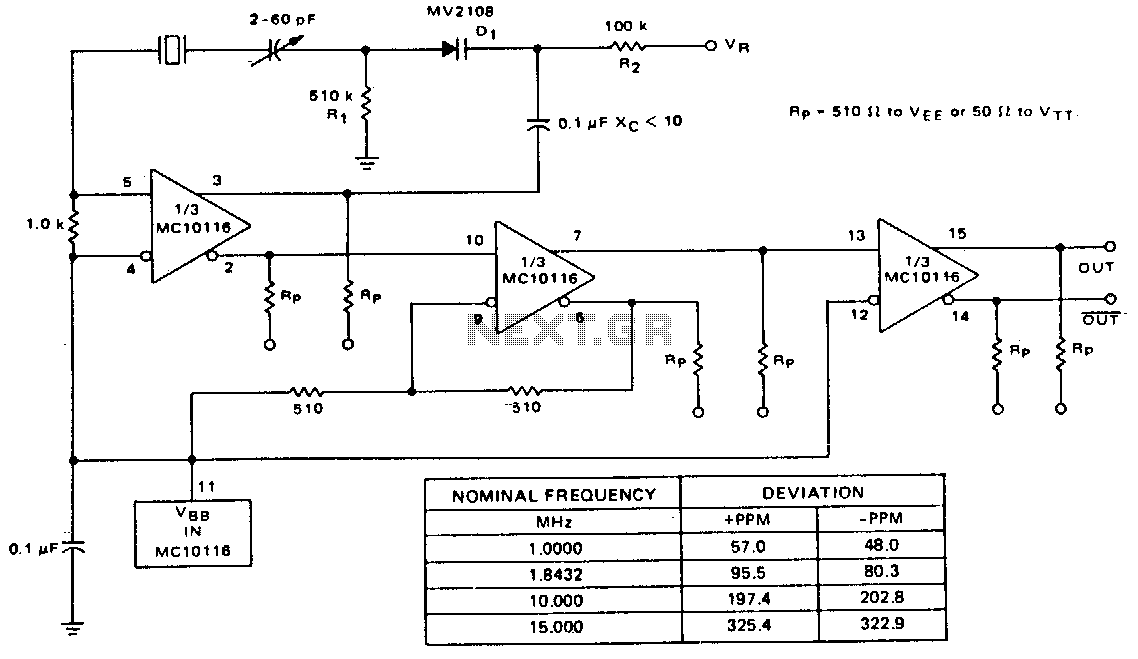
A voltage-variable capacitance tuning diode is connected in series with the crystal feedback path. Adjusting the voltage on the variable resistor (VR) changes the capacitance of the tuning diode, which in turn tunes the oscillator. The 510 kΩ resistor...
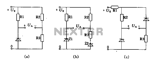
The circuit depicted in Figures A, B, and C demonstrates a high voltage coefficient. When the regulator resistance \( r_z \) is held constant, the bridge configuration achieves an infinite voltage coefficient. In Figure A, the load circuit is...
A linear feedback amplifier that incorporates reactive elements can produce sinusoidal oscillations at a frequency where the loop gain Ab equals -1. The sine wave oscillators examined in this experiment comprise two interconnected components: the amplifier section and the...
The Armstrong oscillator is utilized to generate a sine-wave output with a constant amplitude and fairly stable frequency within the RF range. It is commonly employed as a local oscillator in receivers, as a source in signal generators, and...