
wind meters
The wind meter circuit operates on the principle of differential thermal response between two transistors. Transistors Q1 and Q2 are positioned to have their junctions exposed to the airflow. As the wind flows over these transistors, it cools them, leading to variations in their VCE based on the wind speed. The differential power dissipation between the two transistors is a key factor in determining the output voltage.
The operational amplifier serves to amplify the small voltage differences detected by R10, which is critical for providing a readable output. The output voltage (Fout) is linearly related to the wind speed, allowing for easy interpretation. The scaling of the output voltage to correspond with wind speed can be adjusted by changing the gain of the operational amplifier or by modifying the resistor values in the feedback loop.
It is essential to ensure that the transistors are selected based on their thermal characteristics and response times, as these parameters can significantly affect the accuracy and responsiveness of the wind meter. Additionally, the circuit's power supply must be stable and provide a constant 5V to ensure reliable operation.
Careful consideration must be given to the resistor values used in the circuit. They must be chosen to optimize the sensitivity and range of the wind meter. Using a potentiometer in conjunction with fixed resistors may provide a means to calibrate the device for specific applications or environmental conditions.
The schematic diagram accompanying this description would illustrate the arrangement of the components, including the transistors, resistors, operational amplifier, and the connection to the voltmeter, providing a clear visual representation of the circuit's functionality.This circuit is a circuit diagram gauges simple wind meter. Working principle of this circuit are the transistors Q1 and Q2 are used to feel the wind. The relationship between thermal impedance and the surrounding transistors utilized wind speed here. Transistors Q1 and Q2 is the cable that VCE of Q1 is higher than Q2 and therefore power dissipati on will be higher. The wind causes the cooling so that Q1 VCE of changes. Which ended at different power dissipations and the different variations detected by R10. This voltage opamp and strengthened to generate comparable Fout wind speed. To air is still Fout will 0V and at 75 m / s wind speed will Fout 2. 5V. A voltmeter FSD Fout 3V is connected across the terminal and ground can be used as a screen. The following is a schematic drawing: The circuit requires 5V DC voltage. To work properly, the air must pass through two transistors (Q1 and Q2). Most of the resistors are not used here are the standard values. So, you should use a combination (series or parallel) resistors to achieve certain values. Please note that the resistor values is very important in this circuit. 🔗 External reference
Related Circuits
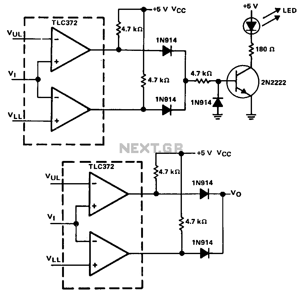
A window detector is a specialized comparator circuit designed to detect the presence of a voltage between two prescribed limits, which defines a voltage window. This circuit is constructed by logically combining the outputs of two single-ended comparators using...
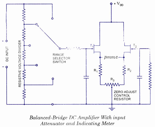
The electronic multimeter is a versatile general-purpose instrument capable of measuring both DC and AC voltages, as well as current and resistance. This solid-state device typically includes a built-in power supply for operation on AC mains and often features...
When starting to create pickups, a larger lathe was acquired, while a mini lathe that was intended for sale was repurposed. In the realm of electronics, pickups are essential components, especially in applications such as electric guitars and other stringed...
This is a straightforward circuit. The first stage functions as a crystal receiver, utilizing a germanium detector diode (such as 1N34, although AA119 is more commonly found in Europe); a silicon diode is not suitable. The operating frequency is...
Because it uses few parts, a printed circuit board is not necessary; components can simply be soldered to one another. However, a box is desirable for operating convenience. The case and aerial from a discarded toy walkie-talkie was used...
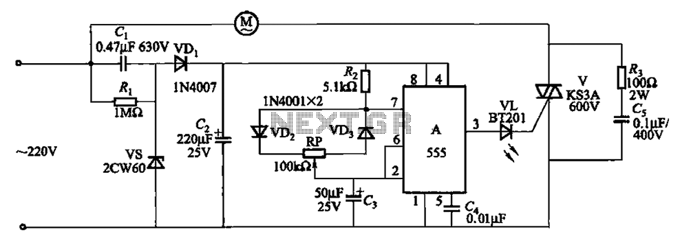
The circuit depicted in Figure 3-8 is designed to control a fan, allowing it to gradually decrease its airflow until it stops completely. This process is repeated in cycles. The circuit utilizes a 555 integrated circuit (IC) configured as...