
Wireless XBee Accelerometer
The wireless tilt mouse project utilizes a 3-D accelerometer to detect tilt movements, which are translated into cursor movements on a PC screen. The system consists of two main components: the transmitter, which incorporates the accelerometer and XBee module, and the receiver, which connects to the PC via an EasyUSB module.
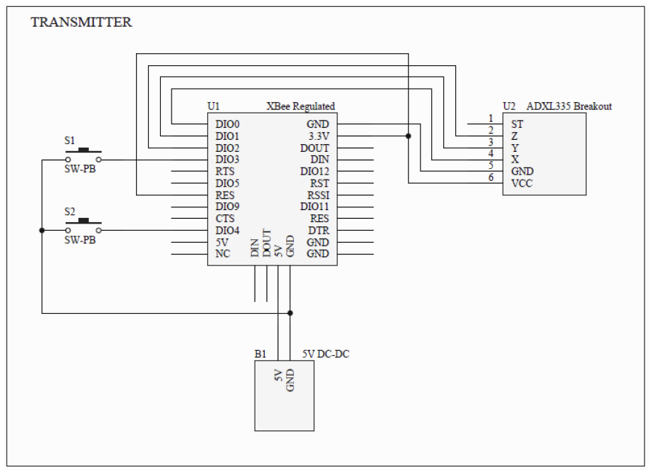
The transmitter is powered by AA batteries and features a simple circuit design that includes the accelerometer, two push-buttons for additional control, and the XBee module for wireless communication. The accelerometer captures the tilt in three dimensions, converting the analog signals into digital data that the XBee module transmits using the ZigBee protocol.
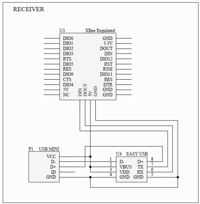
On the receiver side, the second XBee module is configured to receive the transmitted data. This module is connected to the EasyUSB interface, which allows the PC to recognize it as a mass storage device. The EasyUSB module contains the necessary firmware to interpret the incoming data from the XBee and emulate mouse functions without requiring additional software installation on the PC.
Configuration of the XBee modules is performed using a console application, xbee_config.exe, which allows users to set one module as a transmitter and the other as a receiver. This setup is straightforward, requiring users to copy the configuration program and the main application, tiltmouse.exe, onto the EasyUSB module. The application not only facilitates mouse emulation but also provides real-time feedback on the accelerometer data, enhancing user interaction and understanding of the system's operation.
The design emphasizes modularity and ease of assembly, making it accessible for individuals without advanced skills in SMD soldering or embedded programming. All necessary hardware schematics and software source codes are provided, promoting an open-source approach for educational purposes and further development. This project serves as an excellent platform for learning about interfacing accelerometers, configuring wireless communication modules, and managing USB peripherals in a practical application.The present document shows step by step how to easily build an interesting pointing device: the wireless tilt mouse, that allows to control the mouse?s cursor on the PC screen through the tilt of the board itself. The analog data from a 3-D accelerometer and from two push-buttons are acquired, converted and radio transmitted by an XBee module using the standard ZigBee protocol.
On the receiver side there is another XBee module connected to the PC through an EasyUSB module, that allows both file storing and communication on the same interface and it?s seen by the PC as a common mass storage device. In practice there is no need to install any application on the PC: the software that communicates with the XBee and emulates the mouse functions is resident inside the EasyUSB itself and it is automatically recognized by the PC as an USB drive.
The accelerometer/transmitter board is powered by AA batteries. Receiver Config - Put the other XBEE module on the RECEIVER socket. Run xbee_config.exe console and press R to configure the XBEE module as RECEIVER. Press ESC to exit. - Copy the tiltmouse.exe program into the USB device. The wireless tilt mouse transmitter and receiver are done! In order to use it, just run the tiltmouse.exe console on the receiver and plug the batteries on the transmitter. The console, other than emulate the mouse?s functions, also prints on the screen the data acquired from each accelerometer?s axis and push buttons.
This project aims to be an open source hardware/software platform, which can be used for learning about getting accelerometer?s data, configuring XBee modules and managing custom USB peripherals. All the hardware schematics and well commented software source codes are available on the attached project files.
Transmitter Config - Put an XBEE module on the RECEIVER socket and plug the USB cable into the PC. Wait for the automatic installation of the device as a common USB mass storage device. - Copy the xbee_config.exe console into the USB device. Run xbee_config.exe console and press T to configure the XBEE module as TRANSMITTER. Press ESC to exit. - Take off the XBEE module from the RECEIVER socket and place it into the TRANSMITTER socket. In order to design a fast and easy-to-build platform, only breakout boards and modular components are used.
Specific skills like SMD soldering and embedded software programming are not necessary. 🔗 External reference
Related Circuits
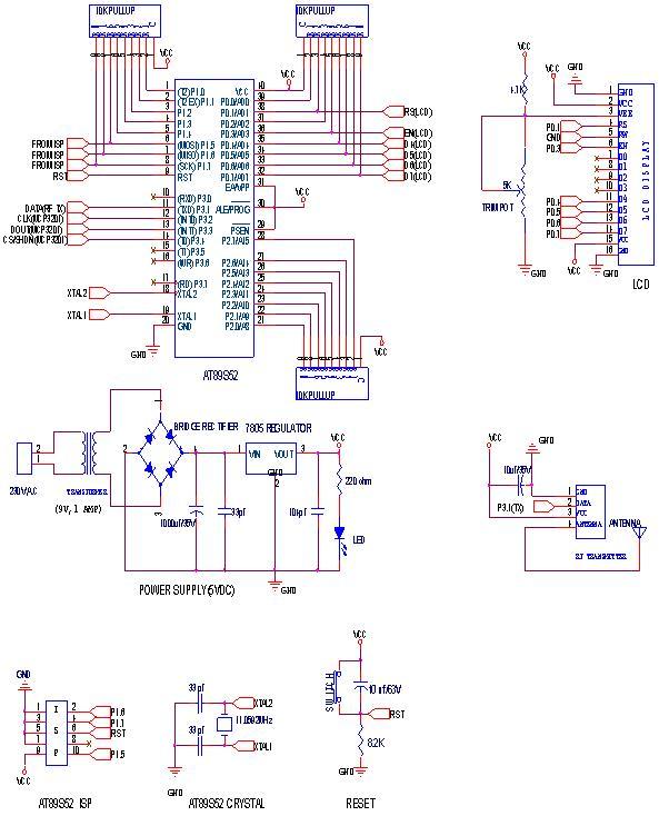
This circuit is a wireless car alarm system constructed using two modules: a transmitter module and a receiver module. It operates on FM radio waves and is suitable for vehicles with a power supply of 6-12VDC. A voltage stabilizer...
The following circuit illustrates a Wireless Car Alarm Circuit Schematic Diagram. Features include the ability to detect sounds within a 20-meter radius, a 1/16 wavelength antenna, and the capability to transmit radio signals up to 2 kilometers. Q1 serves...
RF Wireless Data Transfer communication circuit diagram. A wireless communication interface was implemented to facilitate data transfer from one point to another using RF technology. The RF Wireless Data Transfer communication circuit utilizes radio frequency (RF) technology to establish a...
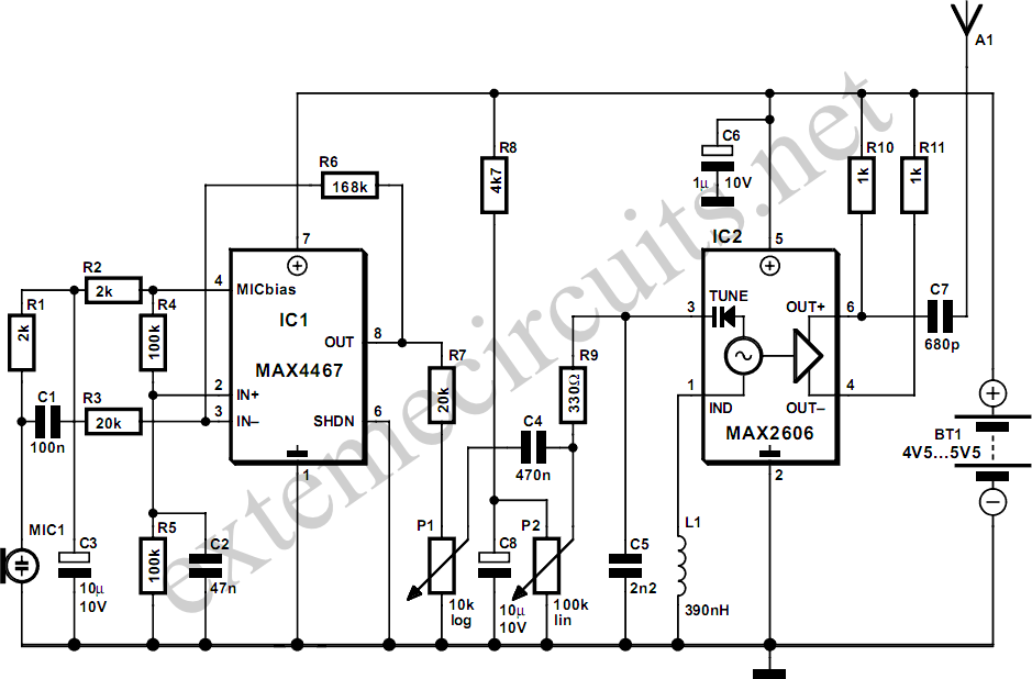
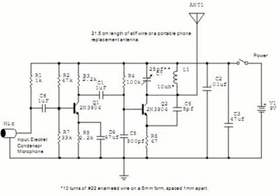
This project involves a simple and cost-effective transmitter designed for hobbyists and home experimenters, capable of transmitting speech over a short distance. It functions as a cordless microphone, utilizing two integrated circuits from Maxim. The first IC, MAX4467, acts...
The circuit is drawn for measurement of acceleration from 1000 mg until + 1000 mg. It can be placed in the car and be supplied from the sheath of the electric lighter. The circuit includes one indicative LED and...
Here's a way to get a short range bidirectional RF (Radio Frequency) channel on a microcontroller, using the controller's tristatable I/O pins and on-chip comparator with a few passive components. The range with the firmware and simple I came...