
Light Bus speed detecting circuit diagrams

The minibus odometer circuit operates by utilizing a combination of electronic and mechanical systems to accurately measure and display vehicle speed and distance traveled. The pulse signals generated by the speed detection mechanism are crucial for the proper functioning of the odometer and speedometer. These pulse signals are typically produced by a sensor that detects the rotation of the vehicle's wheels or transmission output shaft.
Upon generation, the pulse signals are sent to the NC1 instrument cluster, which serves as the primary interface for the driver. The signals travel through the dash panel, where they are routed to the U1 electronic signal processing unit. This processing unit is responsible for interpreting the incoming pulse signals, converting them into meaningful data that reflects the vehicle's speed and distance.
The U1 unit employs various electronic components, such as microcontrollers or dedicated signal processing ICs, to analyze the frequency and duration of the received pulse signals. This data is then used to calculate the vehicle's speed in real-time, which is displayed on the speedometer. Additionally, the odometer function accumulates these signals over time to compute the total distance traveled, which is shown on the odometer display.
The final output is then transmitted to an electromagnetic meter, which uses electromagnetic induction principles to visually represent the speed and distance. This combination of electronic processing and mechanical display provides a reliable and efficient means for drivers to monitor their vehicle's performance. Overall, the integration of these systems results in a modern odometer that enhances the driving experience by providing accurate and real-time information. As shown below, is described in a minibus odometer circuits, the odometer and speedometer is electronic, mechanical integration combination of new instruments. Pulse signal out put from the locomotive speed detecting means, away from the NC1 instrument cluster, after the dash panel through to the core of U1 electronic signal processing system for processing, driving the electromagnetic meter shows mileage and speed.
Related Circuits
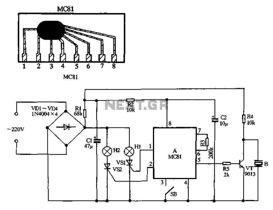
A 220V AC power supply is utilized with a VDI ~ VD4 bridge rectifier, which provides electricity to the lights Hl and H2. The circuit includes two resistors, Rl and R2, that act as current-limiting components for the capacitors...
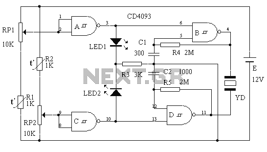
This circuit is a two-way alarm system that utilizes a Schmitt IC, featuring responsive sound and light indicators. It is compact, energy-efficient, and consists of only 13 components, making it a cost-effective solution. The circuit is divided into two...
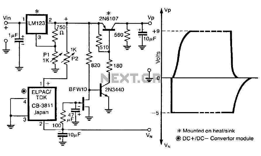
The control circuit is designed to operate by doubling a positive supply, which activates the first door when powered on and deactivates when the first drain is engaged, as illustrated in the accompanying figure. This circuit incorporates the LM123,...
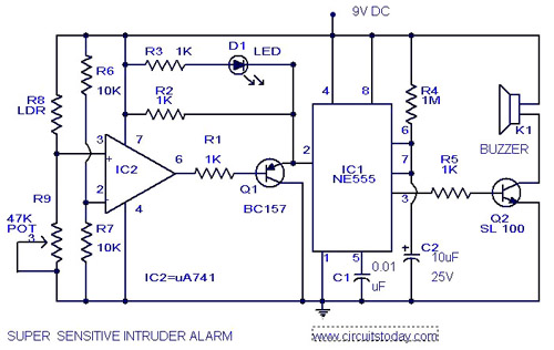
The circuit diagram represents an ultra-sensitive intruder alarm. A shadow from an intruder passing nearby is sufficient to trigger the alarm. The operational amplifier IC2 (uA 741) is configured as a sensitive comparator, with its set point determined by...
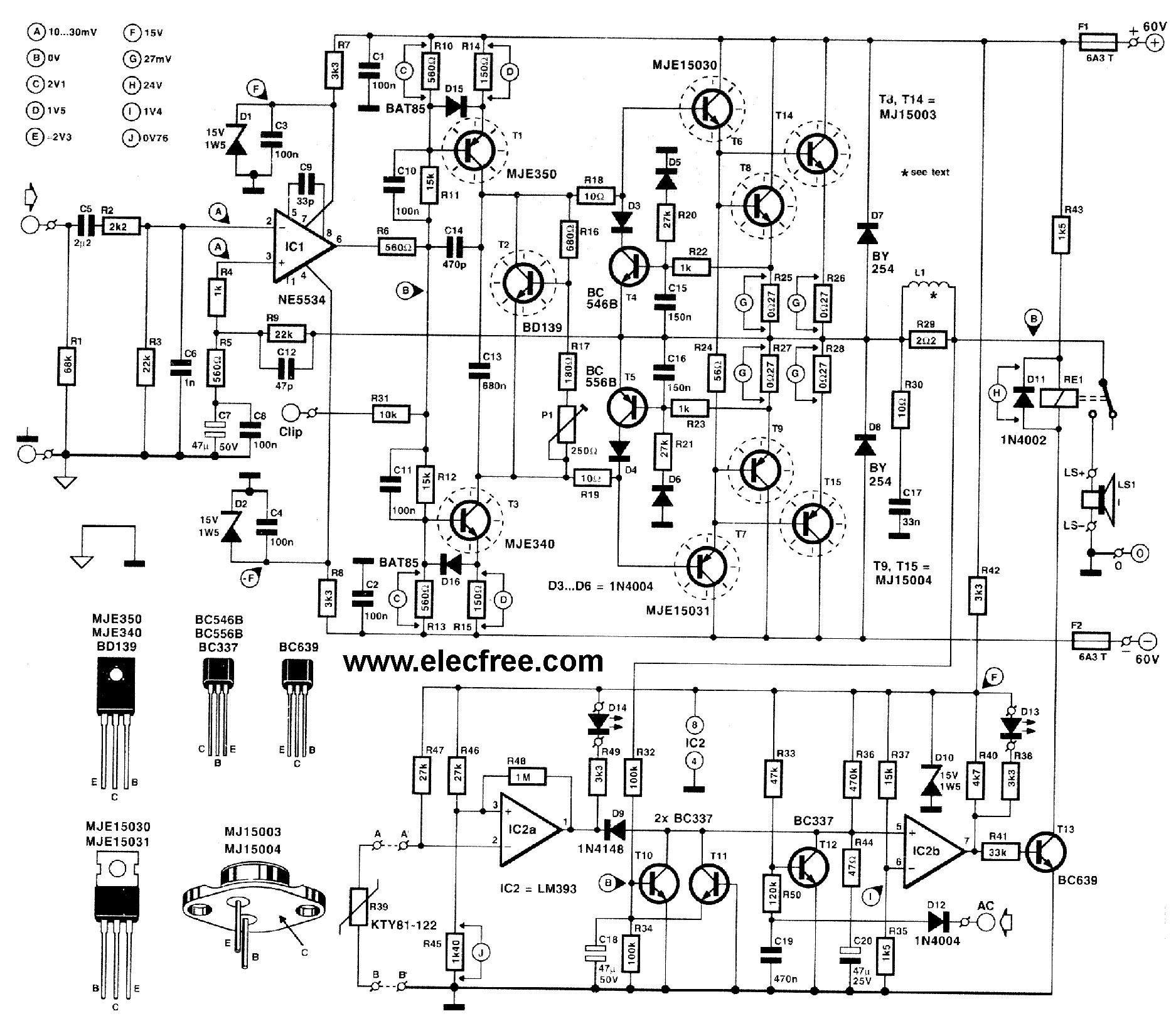
This circuit is designed for friends who are interested in high-power amplifier circuits. It can deliver approximately 300 Watts RMS and operates as an OCL (Output Capacitor-Less) Class AB amplifier, providing high sound power while systematically protecting the loudspeaker...
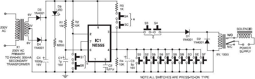
A simple electronic key code lock circuit that requires few external components can be constructed using this schematic diagram. This electronic key code lock circuit is based on a common 555 timer circuit and other standard components. This low-cost...