
10 band equalizer

The equalizer circuit is structured to effectively manage audio signals across a wide frequency range, making it versatile for various audio applications. The ten-band equalization allows for precise control over the audio output, enabling users to tailor the sound to their preferences or specific acoustic environments. The use of both passive and active filters ensures that the design remains compact while still achieving the desired frequency response.
The active filter, which is critical for managing the lowest frequency band, utilizes an operational amplifier to provide the necessary gain without the need for large inductors, which can introduce unwanted size and complexity. The passive filters, being identical in design, simplify the manufacturing process while allowing for easy adjustments to the frequency response by merely changing component values.
The adjustable input impedance and amplification settings provide flexibility, allowing the equalizer to interface with various audio sources and maintain optimal signal integrity. The inclusion of potentiometers for input level adjustment ensures that users can fine-tune the output, especially when integrating with other audio equipment that may have differing output levels.
The choice of operational amplifiers is crucial for maintaining low noise levels and high fidelity in audio processing. The specified op-amps are known for their performance in audio applications, providing a reliable foundation for the equalizer's functionality. The requirement for a regulated 15 V supply ensures stable operation, which is essential for high-quality audio processing.
Overall, this equalizer design is a robust solution for enhancing audio performance in a variety of settings, combining advanced filtering techniques with user-friendly controls for optimal sound management.The equalizer presented in this article is suitable for use with hi-fi installations, public-address systems. mixers and electronic musical instruments. The relay contacts at the inputs and outputs, in conjunction with S2, enable the desired channel to be selected.
The input may be linked directly to the output, if wanted. The input impedance and amplification of the equalizer are set with S1 and S3. The audio frequency spectrum of 31 Hz to 16 kHz is divided into ten bands. Ten bands require ten filters, of which nine are passive and one active. The passive filters are identical in design and differ only in the value of the relevant inductors and capacitors. The requisite characteristics of the filters are achieved by series and parallel networks. The filter for the lowest frequency band is an active one to avoid a very large value of inductance. It is based in a traditional manner on op amp A1. The inductors used in the passive filters are readily available small chokes. The filter based on L1 and L2 operates at about the lowest frequency (62 Hz) that can be achieved with standard, passive components.
The Q(uality) factor of the filters can, in principle, be raised slightly by increasing the value of R19 and R23, as well as that of P1 P10, but that would be at the expense of the noise level of op amp IC1. With component values as specified, the control range is about ±11 dB, which in most case will be fine.
A much larger range is not attainable without major redesign. The input level can be adjusted with P1, which may be necessary for adjusting the balance between the channels or when a loudness control is used in the output amplifiers. Several types of op amp can be used:in the prototype, IC1 is an LT1007, and IC2, an OP275. Other suitable types for IC1 are OP27 or NE5534; and for IC2, AD712, LM833 and NE5532. If an NE5534 is used for IC1, C2 is needed; in all other cases, not. The circuit needs to be powered by a regulated, symmetrical 15 V supply. It draws a current of not more than about 10mA. 🔗 External reference
Related Circuits
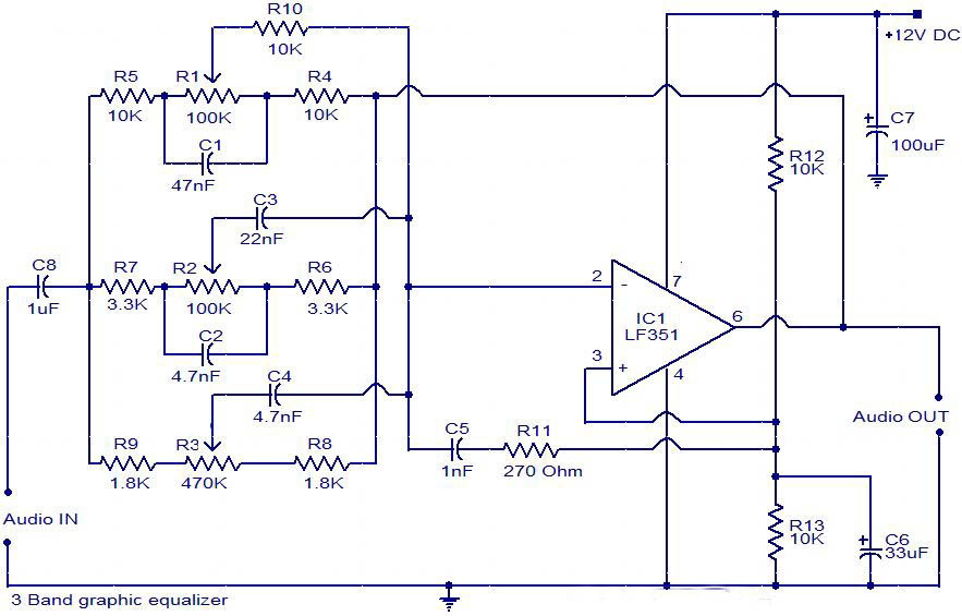
The circuit is a diagram of a simple three-band graphic equalizer circuit. An IC known as the LF351 is utilized in this design. The three-band graphic equalizer circuit is designed to adjust the amplitude of audio signals across three distinct...
This wideband jammer simultaneously blocks all transmissions within a desired band by sweeping across the specified frequency range, starting from the lowest frequency to the highest. A linear sawtooth signal is applied to the modulator in the FM transmitter....
The scope of the AM transmitter is designed to handle amplitude modulated (AM) double sideband (DSB) signals. A standard AM signal consists of a carrier wave and two symmetrically spaced sidebands. The two sidebands carry the same amplitude and...
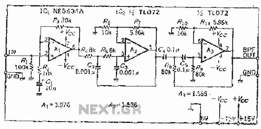
The filter incorporates a zoom function, with a front satin amplifier magnification calculated as d = 10/2.515 = 3.97, which results in a total beam compared to a 10 times magnification. The low-pass filter parameters are specified as a...
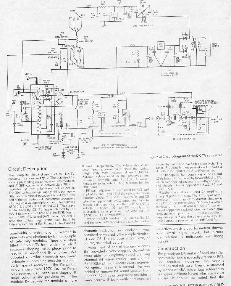
DX TV enthusiasts often encounter crowded VHF bands. In such cases, reducing the TV receiver bandwidth enhances selectivity. Another benefit of bandwidth reduction is an improved signal-to-noise ratio, resulting in less noise and distortion in the DX TV picture....
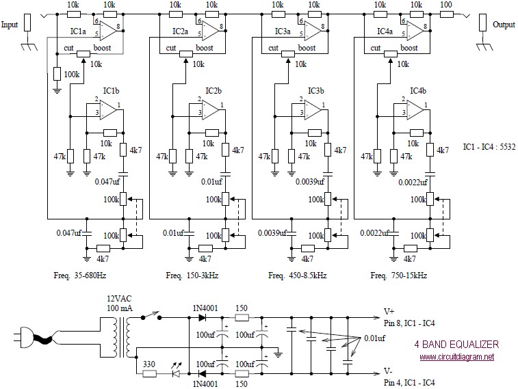
The following diagram illustrates a four-band blaster circuit. This blaster is utilized to enhance sound fidelity, emphasize specific instruments, eliminate unwanted noise, or create entirely new and distinct timbres. The four-band blaster circuit is designed to manipulate audio signals across...