
10 Minute Id Timer

The described circuit utilizes a standard 555 timer IC configured in a monostable or astable mode to periodically identify a transmitter. The operational principle involves the timer generating a pulse every 10 minutes, which is determined by the external resistor and capacitor values connected to the timing pins of the IC.
The circuit's adjustable charge and discharge paths allow for fine-tuning of the timing interval, thereby enhancing flexibility in various applications. The use of a tantalum capacitor (C3) is specified, as it provides stable capacitance and improved performance in timing circuits compared to standard electrolytic capacitors, particularly in terms of size and leakage current.
The relay utilized in this circuit is a small 5-volt reed relay, which is suitable for switching low-power signals. The relay is activated by the output of the 555 timer, allowing it to control the power to the transmitter or other connected devices. The choice of a reed relay ensures quick actuation and minimal power consumption, making it ideal for battery-operated applications.
Overall, this 555 timer circuit is designed to efficiently manage the periodic identification of a transmitter with adjustable timing and reliable switching capabilities, making it suitable for various electronic projects and applications. Designed to automatically identify a transmitter every 10 minutes, this 555 circuit has adjustable charge and discharge paths. The IC should be a standard 555 type, not a CMOS type. C3 should be tantalum. The relay is a small 5-V reed type.
Related Circuits
This timer can provide a time delay ranging from 10 minutes to 12 hours. The time delay is adjustable via a rotary switch, and upon completion of the timing cycle, a relay is energized and remains latched until the...
The following circuit illustrates a repeating interval timer circuit diagram utilizing the CMOS 4060 integrated circuit (IC). Features include its foundation on the CMOS 4060 IC and a 14-bit binary counter. The CMOS 4060 IC is a versatile component widely...
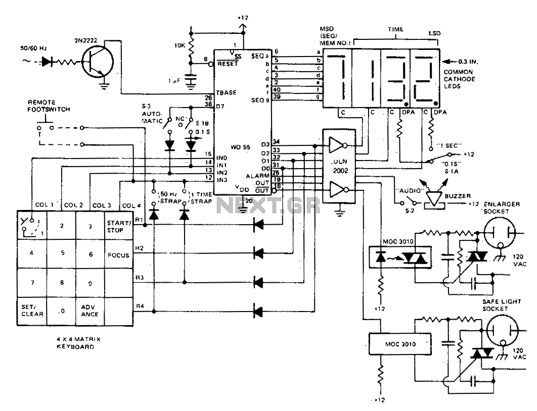
The darkroom timer/controller utilizes a minimal number of external components, including a display, a digit driver, a keyboard, and output switching devices. A 4-digit common-cathode LED display is preferred for use in darkroom settings. The time base is generated...
A simple two tone water alarm that is light enough to be worn on the upper arm of a sleeper is described. It uses two LMC555 CMOS timer chips followed by a complimentary pair of emitter followers to drive...
The output of the transformer has been calculated to be 125 times higher than the input, based on the ratio of 1000 to 8. Given an input of 12V, the expected output should be 1500V, although there is some...
The purpose of this circuit is to power a lamp or other apparatus for a specified duration (30 minutes in this case) and then turn it off. It is particularly useful for reading in bed at night, as it...