
Long Duration Timer
The timer circuit utilizes the CD4060 IC to achieve an adjustable timing function through a combination of resistors and capacitors that determine the oscillation frequency. The rotary switch allows users to select the desired time delay, which is crucial for applications requiring precise control over timing. The binary counter nature of the CD4060 means that as each output is activated, the timing intervals increase exponentially, allowing for a wide range of time delays with minimal component changes.
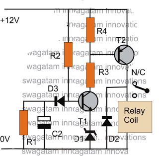
The relay used in the circuit must be suitable for the load being controlled, with consideration given to the current and voltage ratings. The driver transistor (T1) should be chosen based on the relay's coil current requirements, ensuring that it can handle the load without overheating or failing. Additionally, the use of diodes (such as D2) is critical for protecting the circuit from back EMF generated by the relay coil when it is de-energized.
The inclusion of indicator LEDs (green for timing and red for relay activation) provides visual feedback to the user, enhancing the usability of the circuit. The reset functionality, facilitated by the push switch, allows for easy reinitialization of the timer, making the circuit adaptable for repeated use in various applications.
Overall, this timer circuit design offers a reliable and flexible solution for time delay applications, with the potential to be further customized based on specific user requirements or load characteristics.This Timer can give a time delay from 10 minutes to 12 hours. The time delay can be selected using a Rotary switch and when the timing cycle completes, relay energizes and remains latched till the circuit resets. This circuit finds various applications like battery charging or to control lab equipments. Timing cycle is not so precise and a variati on of one to 3 minutes can be expected. Main element of the circuit is the popular Binary counter IC CD4060. It is the 14 stage Oscillator cum binary counter cum frequency divider with an inbuilt oscillator which oscillate depending on the values of the resistor connected to its pin 10 and capacitor at pin 9. When the timing cycles completes, output of the IC goes high. This output can be used to drive loads such as relay through a driver transistor. Since IC 4060 is a binary counter, each output turns high with a time delay double that of the previous one and remains high for the same duration.
So any of the 10 outputs can be used to get the required time delay. Output Q 10 is omitted in the IC itself so that the time delay of Q11 (Pin 1) output is 4 times higher than that of Q9 (Pin 15). At power on IC1 resets through C1 and R2 and starts oscillations. Q3 output (Pin7) turns high first which is indicated by the blinking of Green LED. Each output then turns high as follows: When the output turns high, transistor T1 conducts and activates the relay.
Load can be connected through the Common and NC contacts of the relay so that when the relay turns on, load disconnects. Red LED indicates the activation of relay. When the output turns high, diode D2 conducts and inhibits the oscillator and IC1 latches with the high output and the relay remains energized till resetting.
Push switch can be used to reset IC1 if required. Circuit can be powered using 9 volt DC. 🔗 External reference
Related Circuits
The purpose of this circuit is to power a lamp or other appliance for a specified duration (30 minutes in this case) and then automatically turn it off. This feature is particularly useful for reading in bed at night,...
Generating long delays of several hours can be accomplished by using a low frequency oscillator and a binary counter as shown below. A single Schmitt Trigger inverter stage (1/6 of 74HC14) is used as a squarewave oscillator to produce...
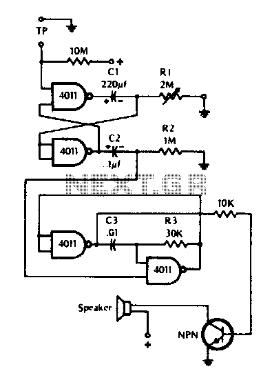
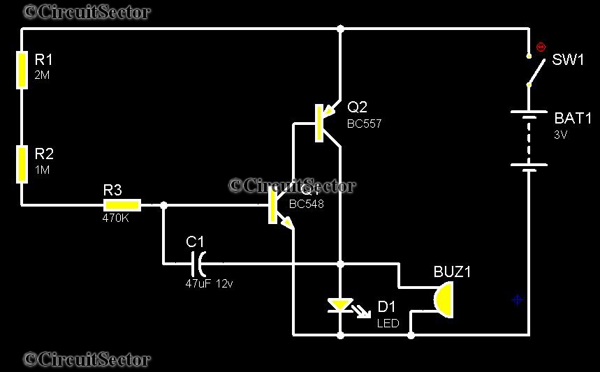
The timer can be utilized for time intervals of up to seven minutes. Activation is achieved by touching the turn-on plate, after which an alarm will sound for a brief duration upon the completion of the selected time, followed...
The post discusses a simple delay ON circuit that enables a connected load at the output to be activated with a predetermined delay after the power switch is turned ON. This circuit can be utilized in various applications that...
This circuit illustrates the NE555 timer used in a light-sensitive alarm sensor circuit diagram. Features include the ability to detect a sudden shadow falling on the sensor. The NE555 timer is a versatile integrated circuit widely utilized in various timing,...
Telephones are declining globally; however, India has over 350 million mobile phone users, alongside a significant number of traditional telephone users. This telephone timer is designed to save costs by controlling unnecessary time spent during phone calls. This simple...