
12 Volt Supply Regulated

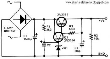
The described circuit employs a 13-volt zener diode (D2) to achieve voltage regulation. The zener diode functions by maintaining a stable output voltage across its terminals when reverse-biased, effectively clamping the voltage to approximately 13 volts. In this configuration, the voltage drop across the base-emitter (b-e) junction of the transistors is approximately 0.7 volts. This drop is typical for silicon transistors and is necessary for their operation in the active region.
The output voltage available from the circuit is approximately 12.3 volts, which is calculated by subtracting the 0.7 volts from the zener voltage. This output is suitable for powering various electronic loads, with the circuit capable of supplying a maximum current of 500 mA.
The amplified zener circuit design enhances the current drive capability of the zener diode, allowing it to handle higher loads without compromising voltage stability. The inclusion of transistors in the design serves to amplify the current, enabling the circuit to maintain the desired output voltage even under varying load conditions.
In practical applications, this circuit can be utilized in power supply systems where a stable voltage is crucial, such as in sensor applications, microcontroller power supplies, or other electronic devices requiring a regulated voltage source. Proper heat dissipation measures should be considered, as the transistors may generate heat during operation, especially when supplying currents near the maximum rating.This circuit above uses a 13 volt zener diode, D2 which provides the voltage regulation. Aprroximately 0.7 Volts are dropped across the transistors b-e junction, leaving a higher current 12.3 Volt output supply. This circuit can supply loads of up to 500 mA. This circuit is also known as an amplified zener circuit. 🔗 External reference
Related Circuits
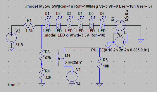
A suitable method to sense when some LEDs in a garage door opener are illuminated. A power source, potentially the same as Vout, connects to a 1.5 kΩ resistor, which then connects to six LEDs followed by a transistor....
This circuit is a series-FET Voltmeter known as FETVM. The FETVM is designed to replace the function of a vacuum tube voltmeter (VTVM) while simultaneously providing a means to clean the appliance cord. Additionally, the drift rate of this...
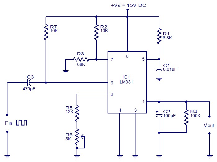
The following circuit illustrates a Frequency Voltage Converter Circuit. This circuit is based on the LM331 IC and operates with a supply voltage of 15V DC. The Frequency Voltage Converter Circuit utilizes the LM331 integrated circuit, which is designed for...
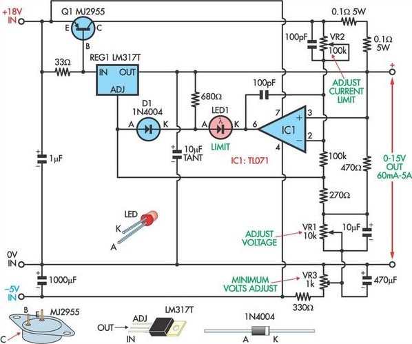
This circuit, based on a National Semiconductor application note, utilizes an LM317 3-terminal regulator (REG1) due to its integrated over-current and over-temperature protection features. The output current is amplified to slightly over 5A using the MJ2955 transistor (Q1). The...
This circuit is a small +5V power supply, which is useful when experimenting with digital electronics. Small inexpensive wall transformers with variable output voltage are available from any electronics shop and supermarket. Those transformers are easily available, but usually...
This circuit can be utilized in applications requiring high current and low ripple voltage, such as in high-powered Class AB amplifiers where high-quality audio reproduction is essential. Q1 and Q2, along with resistor R2, function as a power Darlington...