
5 Digit Alarm Keypad

The described circuit utilizes a keypad interface to activate a modular burglar alarm system. The keypad must consist of a common terminal and individual connections for each key, specifically designed to facilitate the selection of a unique code from a set of five keys. The configuration allows for a significant number of possible combinations, as it can incorporate non-numeric symbols, resulting in nearly 100,000 different codes.
The connection of the keypad to the circuit involves linking the selected keys, labeled A, B, C, D, and E, to designated points on the circuit. The common terminal is connected to resistor R1, while the remaining keys are wired to point F. This setup ensures that when the designated sequence of keys (A, B, C, and D) is pressed in the correct order within a time frame defined by capacitor C1 and resistor R2, the system will activate.
The timing component, consisting of C1 and R2, is critical for the operation of the system, allowing a window of approximately 10 seconds for the user to input the code. When the correct sequence is entered, current flows through resistor R11, which activates transistor Q6. The activation of Q6 subsequently energizes a relay, enabling the alarm system.
Once the relay is energized, it maintains its state by providing base current to Q6 through resistor R12. This self-latching mechanism ensures that the alarm remains activated until it is intentionally deactivated, providing a robust security feature for the burglar alarm system. The schematic design emphasizes simplicity and reliability, making it suitable for various applications beyond just alarm systems.This switch will suit the Modular Burglar Alarm circuit. However, it also has other applications. The Keypad must be the kind with a common terminal and a separate connection for each key. On a 12-key pad, look for 13 terminals. The matrix type with 7 terminals will NOT do. Choose the five keys you want as your code, and connect them to `A, B, C, D & E`. Wire the common to R1 and all the remaining keys to `F`. Because your choice can include the non-numeric symbols, almost 100 000 different codes are available. The Alarm is set using the first four of your five chosen keys. When `A, B, C & D` are pressed in the right order and within the time set by C1 and R2 (about 10 seconds), current through R11 switches Q6 on. The relay energizes, and then holds itself on by providing base current for Q6 through R12. The 12 🔗 External reference
Related Circuits
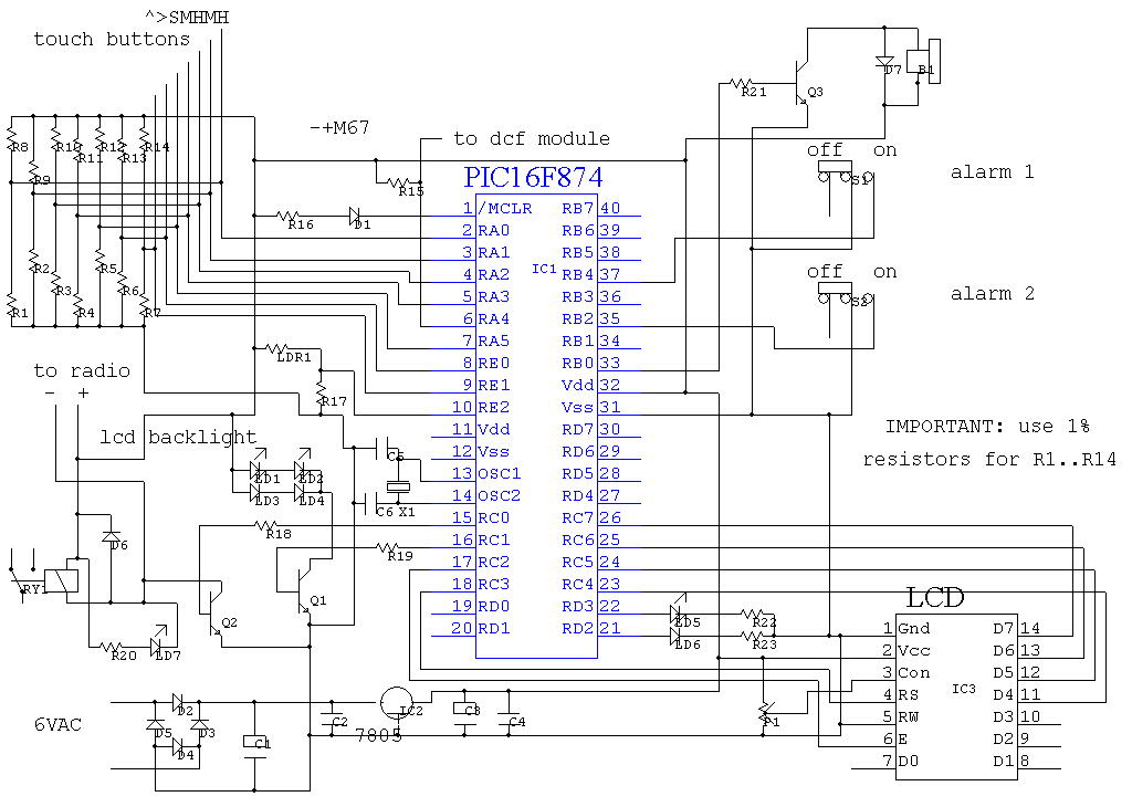
The program utilizes the built-in analog-to-digital (AD) converter of the PIC16F874 microcontroller for sensing touch buttons. The PIC features eight AD ports, with seven designated for the touch buttons and one for light measurement. To receive DCF signals, a...
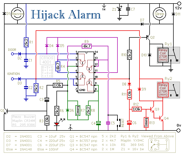
The first circuit was designed for the situation where a hijacker forces the driver from the vehicle. If a door is opened while the ignition is switched on - the circuit will trip. After a few minutes delay -...

This example demonstrates the design of a circuit that incorporates both analog and digital components, features multiple power planes, and utilizes a single ground plane that is divided into analog and digital sections while maintaining a common reference point. The...

This circuit schematic produces a beep and/or illuminates an LED when someone touches the door handle from outside. The alarm will continue to sound until the circuit is switched off. The circuit operates on the principle of capacitive sensing, where...

The TL081 is utilized as a comparator within a Wheatstone bridge circuit. When the resistance of the CDS cell decreases due to light exposure, the output from IC2 prompts the low-frequency oscillators (a) and (b) to produce a 10-Hz...

This is a fire alarm circuit that utilizes a Light Dependent Resistor (LDR) to detect smoke from a fire, making it effective for identifying dark smoke. The risk of fire accidents increases during the summer season, and such incidents...