
555 consisting of portable electronic timing hypnosis massage
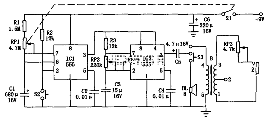
The hypnosis massage device employs two 555 timer ICs configured in astable and monostable modes to generate specific timing intervals. The first 555 timer operates in astable mode, producing a continuous square wave output that serves as the clock signal for the second timer. This clock signal can be adjusted by varying the resistor and capacitor values connected to the 555 timer, allowing users to customize the frequency and duration of the relaxation periods.
The second 555 timer is configured in monostable mode, triggered by the output of the first timer. This timer generates a single pulse of a predetermined duration whenever it receives a trigger signal. The output pulse can be used to activate a massage motor or other therapeutic devices, providing a timed massage experience.
The circuit is designed to be compact and portable, making it suitable for personal use. It can be powered by a small battery, ensuring convenience and ease of use. Additionally, the circuit can be integrated with other components, such as LED indicators or audio signals, to enhance the user experience.
In summary, the hypnosis massage device combines two 555 timers to create a versatile timing circuit that meets the relaxation needs of users through adjustable timing intervals for massage therapy. The design emphasizes portability and user customization, making it an effective tool for personal health and wellness. As shown in FIG hypnosis massage is pocket-sized electronic timing circuit with two 555 timers to form, to meet the health needs of people to relax. Circuit consists of three p arts: a timer circuit, a circuit hypnosis, massage circuit.
Related Circuits
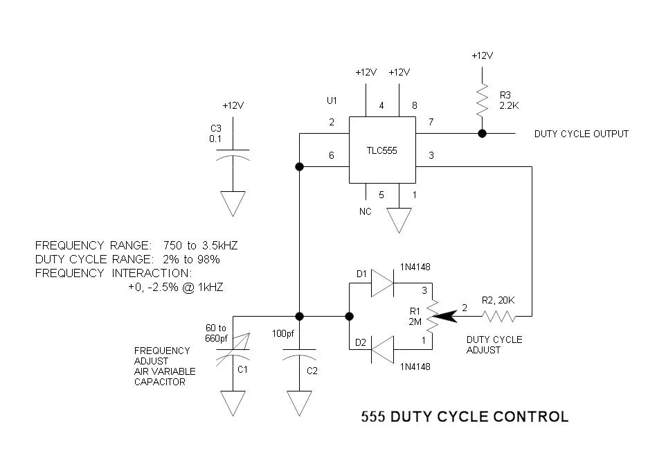
This is a simple oscillator circuit that varies the duty cycle over a wide range without affecting the frequency. It is a variation of the simple 555 astable multivibrator. The oscillator circuit utilizes the 555 timer IC configured in astable...
The primary components of this doorbell circuit include two NE555 timer integrated circuits (ICs). When the switch S1 is pressed momentarily, the loudspeaker emits a bell tone for the duration determined by the time period of the monostable multivibrator...

This stereo balance indicator circuit diagram is designed using a few common external components. The schematic circuit is simple to build and provides a visual indication with LEDs for left, right, and center balance. Outputs from each channel are...
The function of this circuit is to detect a sudden shadow falling on the light sensor and to activate a buzzer when this occurs. The light sensor is designed to monitor ambient light levels. The circuit utilizes a light-dependent resistor...
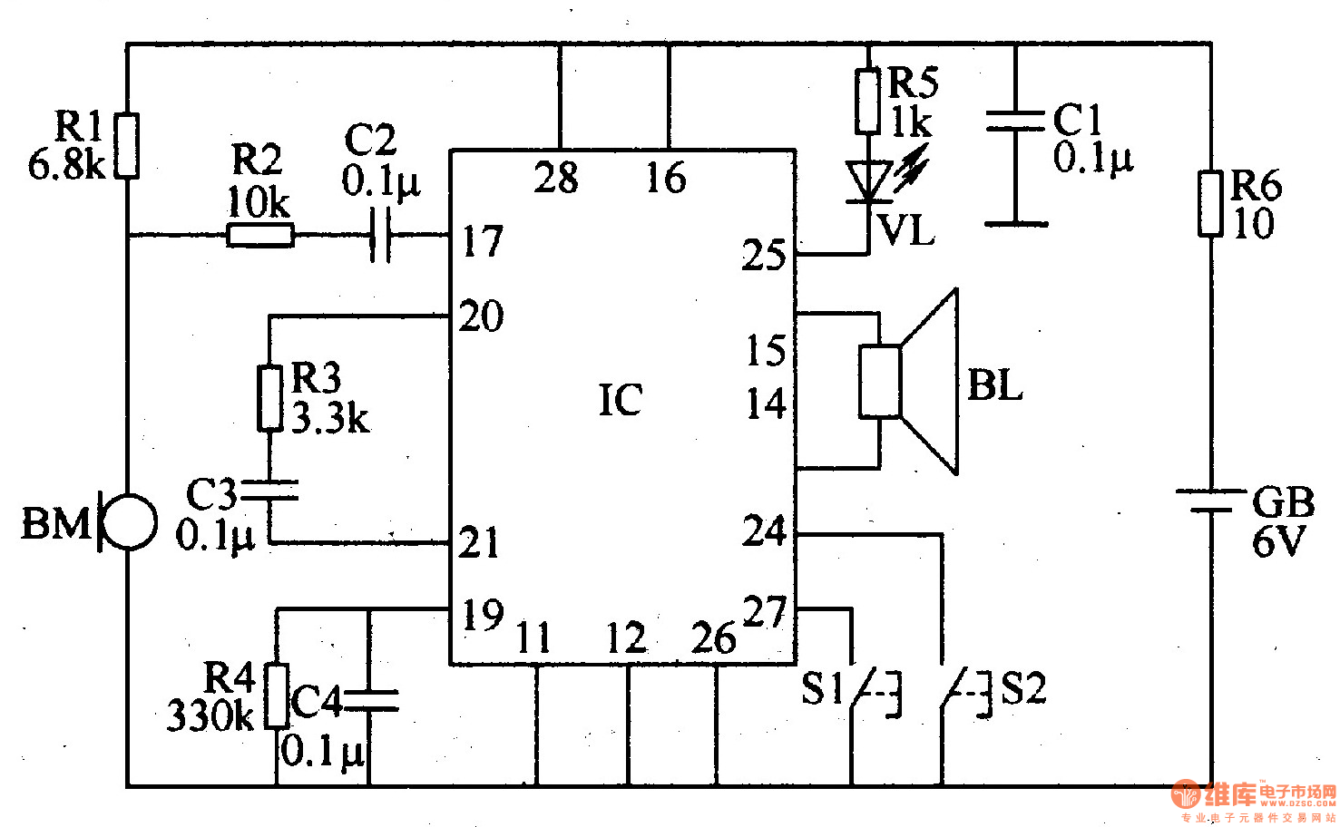
The recordable electronic doorbell consists of a recording and playback integrated circuit (IC), resistors R1-R6, capacitors C1-C4, a microphone (BM), a speaker (BL), control buttons S1 and S2, a battery (GB), and an LED (VL). Resistors R1-R5 should be...

This circuit operates as an astable multivibrator. With switch S9, an octave can be chosen. The tones are set by P1 to P8. Pressing S1 to S8 displays the corresponding note; pressing two buttons at the same time gives...
Warning: include(partials/cookie-banner.php): Failed to open stream: Permission denied in /var/www/html/nextgr/view-circuit.php on line 713
Warning: include(): Failed opening 'partials/cookie-banner.php' for inclusion (include_path='.:/usr/share/php') in /var/www/html/nextgr/view-circuit.php on line 713