
555 Monostable Multivibrator

The described circuit utilizes the 555 timer in its monostable configuration, which is commonly employed in applications requiring a single pulse output in response to a trigger signal. The circuit operates by leveraging the internal comparators and flip-flop of the 555 timer. When the trigger input ("tr") is pulled low, it activates the timer, causing the output pin to transition high. This high state remains for a duration determined by the resistor-capacitor (RC) time constant, which is calculated using the formula:
\[ T = 1.1 \times R \times C \]
where \( T \) is the time the output stays high, \( R \) is the resistance connected to the discharge pin, and \( C \) is the capacitance connected to the threshold and trigger pins.
In this configuration, a capacitor is used to control the timing interval. As the output goes high, the capacitor charges through the resistor until it reaches the threshold voltage, at which point the output goes low, and the capacitor discharges through the discharge pin. The choice of capacitor value and resistor can be adjusted to achieve the desired timing interval.
The negative-edge triggering characteristic of the monostable multivibrator is essential for applications where a pulse is needed in response to a falling edge of the input signal. If the capacitor is replaced with a direct connection to ground, the circuit will respond differently; holding the input low for an extended time can cause the output to oscillate due to the rapid charging and discharging of the capacitor, indicating a shift from a stable one-shot operation to an unstable oscillatory state.
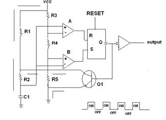
This circuit is widely used in timer applications, pulse-width modulation, and as a delay mechanism in various electronic systems, showcasing the versatility and functionality of the 555 timer in practical electronic designs.This circuit is a monostable multivibrator, or one-shot, made with a 555 timer chip. Click the logic input on the left (the "H"), and the output goes high for a short time, and then it goes low again. A timing interval starts when the trigger input ("tr") is brought low. When this happens, the 555 output goes high. This causes the capacitor to be charged until it reaches 6. 67V. Then, the timing interval ends, the output goes low, and the capacitor is discharged through the "dis" input. The capacitor in front of the trigger input causes the monostable to be negative-edge triggered. If the capacitor is replaced with a wire, and the logic input is held low too long, then the 555`s output will start to oscillate.
🔗 External reference
Related Circuits
A 555 timer IC is utilized as an astable multivibrator, as illustrated in the accompanying figure (A). The threshold input is connected to the trigger input (Pin 2). The resistor R1, resistor R2, and capacitor C1 form the timing...
The operation of the circuit is divided into three parts: low frequency production, high frequency manufacturing, and low frequency extension. The described circuit functions by segmenting its operation into three distinct sections, each serving a specific purpose in the overall...
The schematic shown below is a 555 timer circuit. The NE555 is a well-known integrated circuit that comes in an 8-pin dual in-line package (DIP). There is a vast array of circuits utilizing the 555 IC, which contributes to...
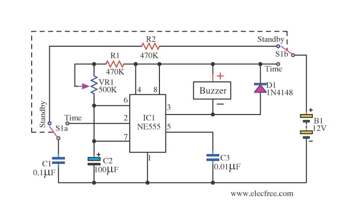
This is a simple and compact timer circuit (Egg Timer) using the IC 555. It features an alarm activated by a buzzer. This mini timer circuit is quite interesting and is referred to as the Egg Timer. The circuit utilizes...
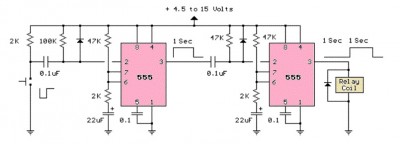
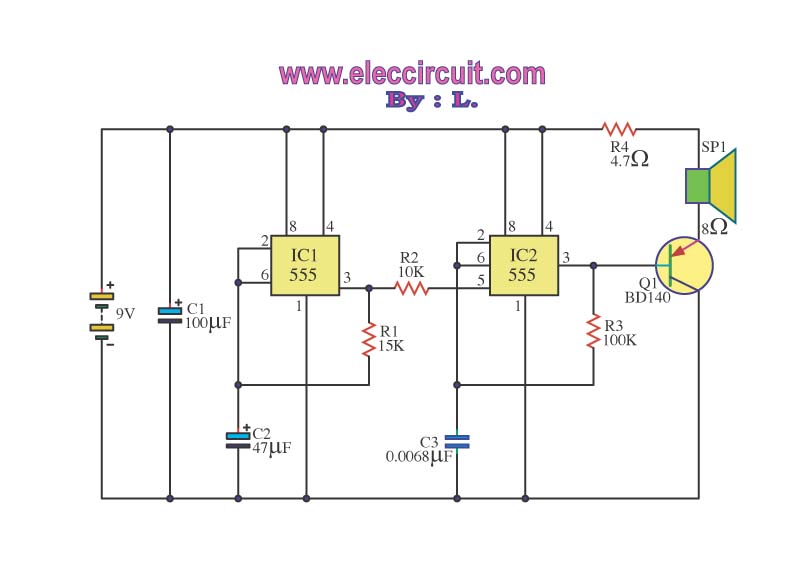
The LM555 timer circuit is similar to the previous design but incorporates two stages, allowing for control over both the pulse width and the delay. The LM555 timer is a versatile integrated circuit widely used in various timer, delay, pulse...
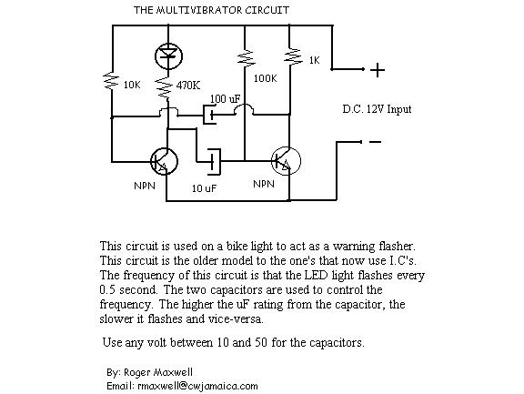
The resistor in series with the LED in the collector circuit of transistor T1 must be 470 ohms, not 470k. To connect a 24V-3W bulb, it is important to note that the resistance of this bulb when lit is...