
60 seconds timer with LEDs

The described circuit employs a 555 timer IC configured in monostable mode to create a timing interval ranging from 0 to 60 seconds. The output of the 555 timer triggers a sequence of events that drives two CD4017 decade counter ICs, which are utilized for LED driving.
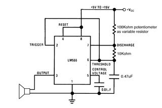
In this configuration, the 555 timer is connected to a resistor-capacitor (RC) network that determines the timing duration. The timing period (T) can be calculated using the formula T = 1.1 * R * C, where R is the resistance in ohms and C is the capacitance in farads. By selecting appropriate values for R and C, the desired timing range can be achieved. For instance, a resistor of 1 MΩ and a capacitor of 100 µF would yield a timing interval close to 60 seconds.
Upon triggering the 555 timer, the output goes high for the duration of the timing period. This output is then fed into the clock input of the first CD4017 IC. The CD4017 is a decade counter that counts from 0 to 9, activating its output pins sequentially as it counts. Each output pin corresponds to a specific LED, allowing for visual indication of the count.
The first CD4017 can be configured to drive ten LEDs, while the second CD4017 can be cascaded to extend the counting capability. The carry-out pin of the first CD4017 can be connected to the clock input of the second CD4017, enabling it to count further once the first reaches its maximum count. This arrangement allows for a total of 20 LEDs to be driven, with each LED illuminating in sequence as the timer counts down.
Power supply considerations for the circuit include ensuring that the 555 timer and the CD4017 ICs are supplied with appropriate voltage levels, typically between 3V to 15V, depending on the specifications of the components used. Additionally, bypass capacitors should be placed near the power pins of the ICs to filter any noise and ensure stable operation.
In summary, the circuit effectively combines a 555 timer for timing control and CD4017 decade counters for sequential LED activation, providing a visual countdown timer that can be utilized in various applications, such as educational projects, displays, or timing indicators.The circuit is a 0-60 second timer using timer 555 and two 4017 for LED driving. 🔗 External reference
Related Circuits
Setting the 555 timer in astable mode results in a continuous series of output pulses. The 555 timer IC, when configured in astable mode, operates as an oscillator, generating a square wave output. This configuration does not require any...

This circuit is a voltage-controlled oscillator (VCO) that utilizes the 555 timer integrated circuit (IC) as its primary component. The 555 timer is configured as an astable multivibrator, enabling it to function as an oscillator. An astable multivibrator is...

The circuit is constructed using the ICM7217 integrated circuit from Intersil, which features a CMOS up/down counter with a four-digit display. The clock generator circuit, IC3, produces a square wave clock signal with a period of one second, available...
A very long time constant is provided by R1 and C1. C1 discharges, and the near-zero voltage at its positive lead is applied to the high-impedance inputs of the circuit. In this circuit, the combination of resistor R1 and capacitor...
This 555 timer circuit toggles a relay when a button is pressed. Pins 2 and 6, which are the threshold and trigger inputs, are maintained at half the supply voltage by two 10K resistors. When the output is high,...
The typical BPM range for music is between 40 and 240 BPM, corresponding to periods of 1500 ms and 200 ms, respectively. A BPM of 120 equates to a period of 500 ms. The circuit requires a resistor R4...