
7-Segment LED Decoder

The CMOS (Complementary Metal-Oxide-Semiconductor) technology combines P-MOS and N-MOS transistors to create efficient and versatile digital logic circuits. The three-terminal NAND gate is a fundamental building block in digital electronics, characterized by its ability to perform the NAND operation, which outputs a low signal only when all inputs are high.
In the construction of a three-terminal NAND gate using CMOS technology, two N-MOS transistors are connected in series between the output and ground, while two P-MOS transistors are connected in parallel between the output and the power supply. The gates of these transistors are connected to the input terminals. When both inputs are high (logic '1'), the N-MOS transistors conduct, creating a path to ground and pulling the output low (logic '0'). Conversely, when at least one input is low (logic '0'), the P-MOS transistors will conduct, allowing the output to be pulled high (logic '1').
The advantages of using CMOS technology for NAND gates include low static power consumption, high noise immunity, and the ability to integrate a large number of transistors on a single chip, making it suitable for modern digital circuits, including microprocessors and memory devices. The universal nature of the NAND gate allows it to be used to construct any other logic gate, thus serving as a cornerstone in digital circuit design.It can be possible and it can be implemented using P-MOS and N-MOS together in a circuit i. e. what is called C-MOS. There we can implement Three Terminal NAND GATE. It is a universal gate which is used commonly so can proceed further. 🔗 External reference
Related Circuits
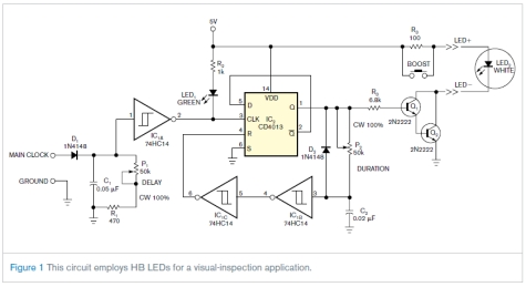
This circuit is not complex, but it was instrumental in an application involving the visual inspection of the spray pattern of fuel injectors for quality and consistency. In this application, xenon strobe lights were unsuitable due to their large...
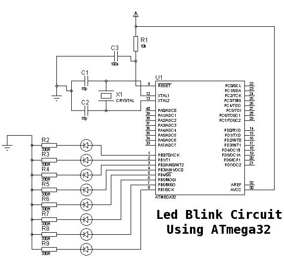
This is a basic tutorial for beginners using the ATmega32 microcontroller to get started. This program can be referred to as a "Hello World" for the ATmega. The ATmega32 microcontroller is a member of the AVR family, widely utilized in...
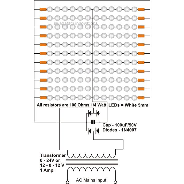
The use of white LEDs for home illumination is gaining popularity due to their high power efficiency. The diagram illustrates a simple circuit configuration that consists of multiple LEDs arranged in both series and parallel. In the LED tube...
The bi-directional sequencer employs a 4-bit binary up/down counter (CD4516) along with two "1 of 8 line decoders" (74HC138 or 74HCT138) to create the well-known "Night Rider" display. A Schmitt Trigger oscillator generates the clock signal for the counter,...
Here's a circuit that takes advantage of the photo-voltaic voltage of an ordinary LED. The LED voltage is buffered by a junction FET transistor and then applied to the inverting input of an op-amp with a gain of about...
The 8-lead plastic mini-DIP LM3909 integrated circuit was developed by National Semiconductor in the mid-1970s. It is a monolithic oscillator specifically designed to flash Light Emitting Diodes (LEDs). By utilizing the timing capacitor for voltage boosting, it can deliver...