
Acid rain monitor

When acidity causes the sensor to generate a voltage, Q1 activates slightly, resulting in a decrease in its drain-to-source resistance. This variation in resistance creates an imbalance in the bridge, which is indicated by meter M1.
The circuit described integrates a bridge rectifier and a voltage regulator to ensure stable power supply to the MOSFET-based sensing circuit. The bridge rectifier converts alternating current (AC) to direct current (DC), providing an unregulated output that is subsequently processed by a 12-volt regulator. This regulated output is essential for the reliable operation of the drain solenoid, which is activated through switch SI.
The sensing mechanism employs a dual-electrode configuration, with one electrode made of copper and the other of lead. This arrangement, in conjunction with the liquid medium, simulates a miniature lead-acid cell. The electrochemical reaction occurring within this cell generates a small voltage, which is subsequently amplified by MOSFET Q1. The performance of the prototype cell yielded a maximum output of approximately 50 µA, indicating the sensitivity and effectiveness of the sensor.
MOSFET Q1 not only amplifies the signal but also plays a crucial role within a Wheatstone bridge configuration. In this setup, Q1 acts as the fourth leg, allowing for precise measurements of resistance changes. When the acidity of the liquid increases, it induces a voltage in the sensor, causing Q1 to turn on slightly. This activation leads to a reduction in the drain-to-source resistance of Q1, resulting in an imbalance within the Wheatstone bridge. The resulting voltage difference is detected and displayed by meter M1, providing a visual indication of the sensor's response to changes in acidity.
In summary, this circuit effectively combines rectification, regulation, and sensor amplification to create a reliable system for monitoring acidity. The integration of a Wheatstone bridge allows for accurate measurement of resistance changes, enabling precise detection of variations in the sensor's output due to changes in the liquid's acidity.A bridge rectifier and 12-volt regulator powers the MOSFET sensing circuit. The unregulated output of the bridge rectifier operates the drain solenoid via switch SI. The sensor itself is built from two electrodes, one made of copper, the other of lead. In combination with the liquid trapped by the sensor, they form a miniature lead-acid cell whose output is amplified by MOSFET Ql. The maximum output produced by our prototype cell was about 50 µ. MOSFET Ql serves as the fourth leg of a Wheatstone bridge. When acidity causes the sensor to generate a voltage, Ql turns on slightly, so its drain-to-source resistance decreases. That resistance variation causes an imbalance in the bridge, and that imbalance is indicated by meter Ml.
Related Circuits

The circuit consists of the MAX1494 digital strain gauge, as illustrated in Figure 5-31. It includes a bridge formed by resistance strain gauges and a temperature compensation sheet. The standard quasi-resistance values Rl and R are incorporated into the...
Using a thermistor in the position shown makes a heat activated sensor. A change in temperature will alter the output of the opamp and energize the relay and light the LED. Swapping the position of the thermistor and 47k...
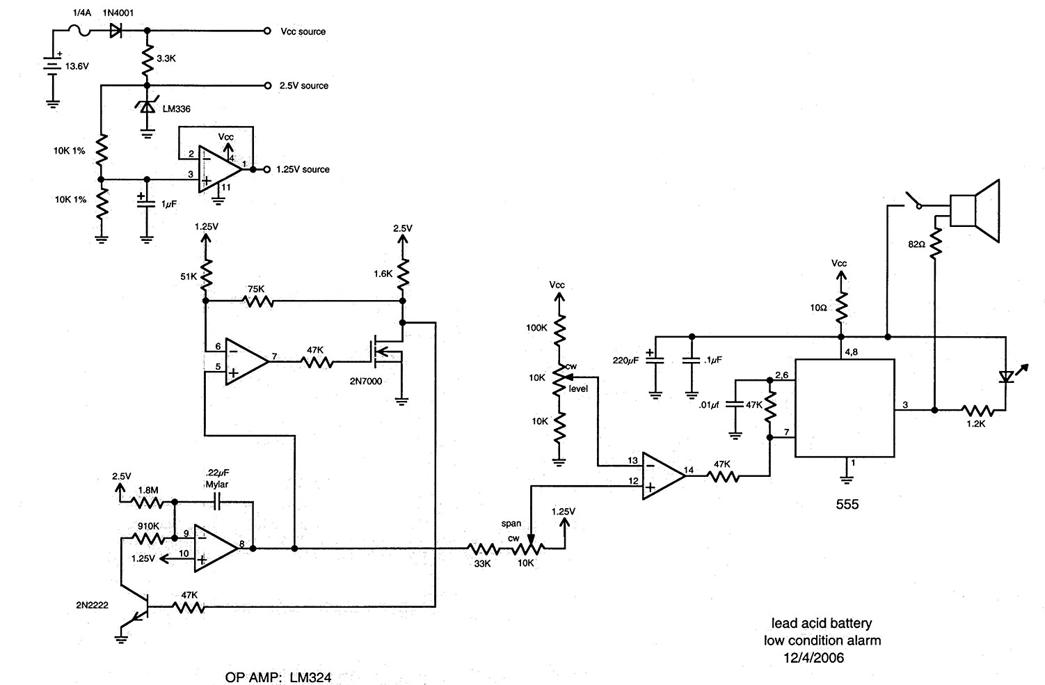
The following circuit is adapted from battery monitors and testers published in The Smith-Kettlewell Technical File (SKTF). The first appearance of this system was "The Smith-Kettlewell Battery Tester, Where Silence is Golden," SKTF, Volume 11, No. 1, Winter 1990....
The schematic indicates that the AccelR8 utilizes only three integrated circuits (ICs). An AVR 8515 microcontroller performs the computational tasks and manages the other circuits. A MAX603 regulates voltage and controls the power-on and power-off functions. The key component...
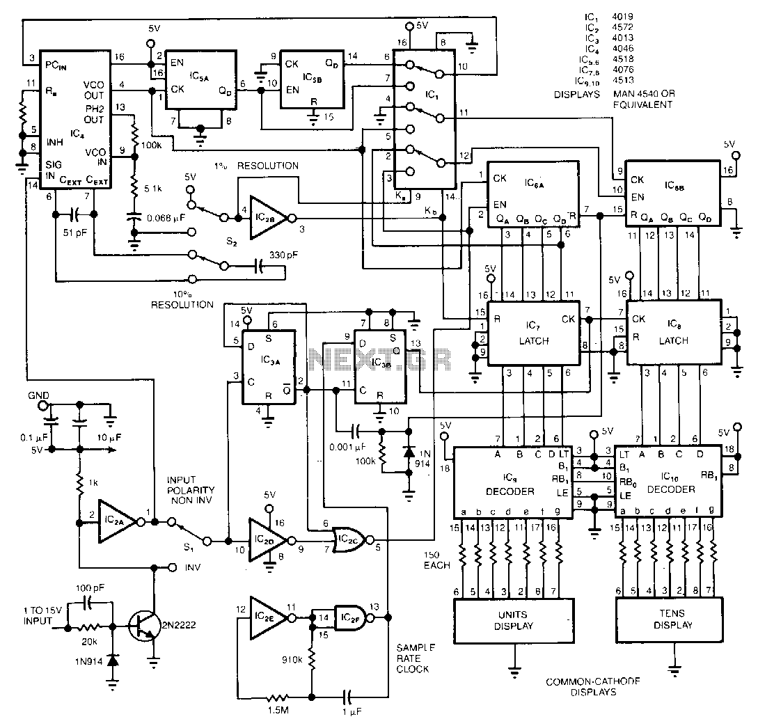
The circuit monitors and displays a digital signal's duty cycle with an accuracy of ±1%. By using switch S2, users can select a frequency range of either 250 Hz to 2.5 kHz with ±1% accuracy or 2 kHz to...
The circuit principle involves using a current transformer for current sensing due to the large AC power load of computers. This setup detects whether there is current in the power line, enabling the determination of its status. The LM393...