
AM/FM/SW active antenna

The active antenna circuit described is intended to enhance the reception capabilities of AM, FM, and shortwave signals, making it particularly useful for portable and low-cost radio receivers. The design incorporates a variable inductor (L1) that allows for tuning to different frequency bands, with specific inductance values suggested for optimal performance. A 470µH inductor is recommended for AM frequencies, while a 20µH inductor is suitable for shortwave reception.
The circuit is powered by a 9-volt battery, which provides the necessary voltage for operation. In scenarios where an external power supply is used, it is critical to include a 0.04µF capacitor in parallel with the power supply connection. This capacitor acts as a bypass, filtering out high-frequency noise that could interfere with signal clarity.
The antenna utilized in this setup is a standard 18-inch telescoping type, which is effective for capturing a wide range of radio frequencies. The compact nature of the telescoping antenna makes it ideal for portable applications, allowing users to extend or retract the antenna based on their reception needs. Overall, this active antenna circuit presents a practical solution for enhancing radio reception across multiple frequency bands.This circuit shows an active antenna that can be used for AM, FM, and shortwave (SW). On the shortwave band this active antenna is comparable to a 20 to 30 foot wire antenna. This circuit is designed to be used on receivers that use untuned wire antennas, such as inexpensive units and car radios. L1 can be selected for the application. A 470uH coil works on lower frequencies ( AM ). For shortwave, try a 20uH coil. The unit can be powered by a 9 volt battery. If a power supply is used, bypass the power supply with a .04uF capacitor to prevent noise pickup. The antenna used on this circuit is a standard 18" telescoping type. 🔗 External reference
Related Circuits
In electronics, filter circuits are primarily used to restrict the passage of certain frequency ranges while allowing other frequency bands to proceed to subsequent stages of the circuit. A high-pass filter circuit permits only frequencies that exceed a specified...
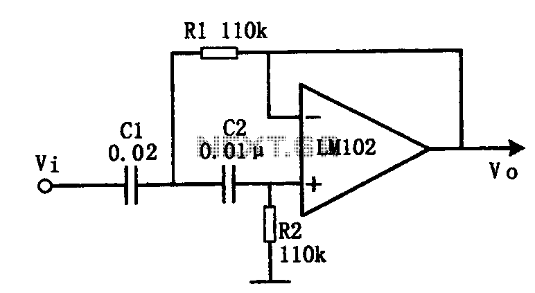
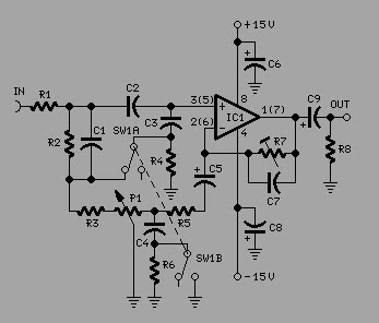
This document presents an active low-pass filter circuit with a cut-off frequency (fc) of 10 kHz. The circuit allows for various values for the ratios of resistors R1 and R2, as well as capacitors C1 and C2. Specifically, it...
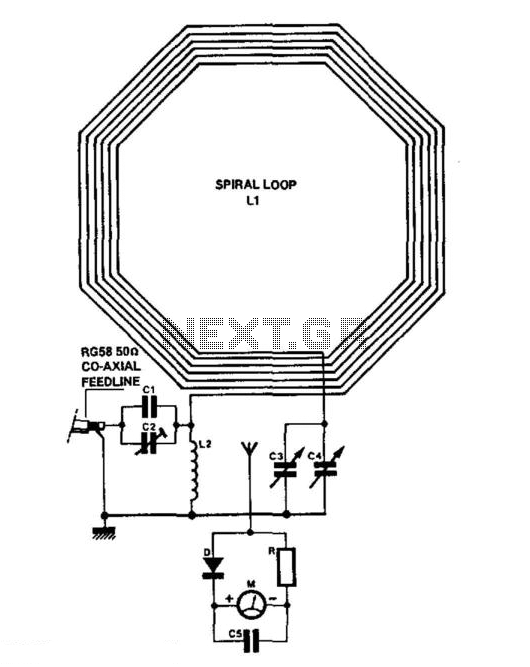
C1 = 3750 pF 500 V silver-mica capacitor. C2 = 100 pF preset capacitor (Jackson C803). C3 = 75 pF variable capacitor (Jackson C809) with a knob. C4 = 12.7 pF variable capacitor (Jackson C16) with a knob. C5...
The antenna used for receiving or transmitting is a crucial component in a communication link. Its performance significantly influences the effectiveness of both the receiver and transmitter. Antennas are reciprocal, meaning an antenna designed for transmission can also function...
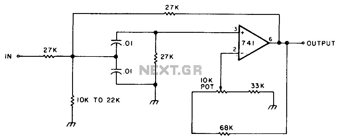
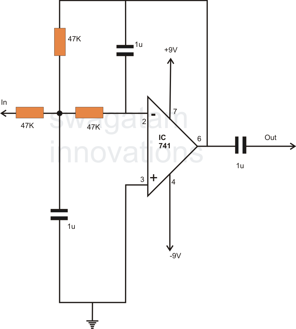
This circuit features adjustable bandwidth with a center frequency of approximately 800 Hz. A 10 kΩ potentiometer is used to adjust the bandwidth, varying from approximately ±350 Hz to ±140 Hz at the 3 dB down points. The circuit operates...
To achieve optimal audio reproduction at various listening levels, it is essential to incorporate tone-setting controls that align with the well-documented characteristics of human auditory perception. Specifically, human ear sensitivity exhibits a non-linear response across the audible frequency spectrum,...