
APM2.0 5V/Vcc Schematic

The APM2.0 circuit features a PWM output section strategically positioned in the upper left corner of the schematic, clearly marked by a heavy purple line. This section is bridged by jumper JP1, which plays a crucial role in the functionality of the circuit. The inclusion of diode D1 is significant, as it facilitates the flow of current through JP1 while simultaneously introducing a voltage drop. The remaining voltage after this drop is labeled as Vcc, which serves as the primary power supply for the circuit.
Components situated outside the delineated purple corner are powered by Vcc, establishing a clear distinction between the power distribution within the circuit. This design is particularly advantageous as it allows the APM2.0 to be powered through USB connections. When connected to a computer or USB hub, the USB port supplies power directly to the APM2.0, ensuring its operation.
Furthermore, the presence of a fuse on the APM2.0 side of the USB connector serves as a protective measure, safeguarding the circuit from potential overcurrent situations. It is essential to note that any 5V source connected to the specified Vcc/5V points outside the purple corner, along with a common ground, can effectively power the APM2.0. This versatility in power sourcing enhances the circuit's functionality and adaptability in various applications.Note that I have separated the PWM Output section into the upper left corner with a heavy purple line that is bridged by the jumper JP1 on the APM2. 0. This is to emphasize that diode D1 passes current through JP1 (and drops voltage). The remaining energy is then called `Vcc`. Everything outside the purple corner is Vcc. This is why the USB will po wer the APM2. 0 when connected to a computer/USB hub. Note the fuse on the APM2. 0 side of the USB connector. In fact, any 5V source connected to any of the indicated Vcc/5V points outside the purple corner (with GND of course) will power the APM2. 0. 🔗 External reference
Related Circuits
A homemade photography LED array is being pursued, ideally configured as 6 series and 5 parallel, operating at 24 volts and 1000mA per row. Each LED row will emit a different wavelength, collectively covering the entire spectrum. The goal...
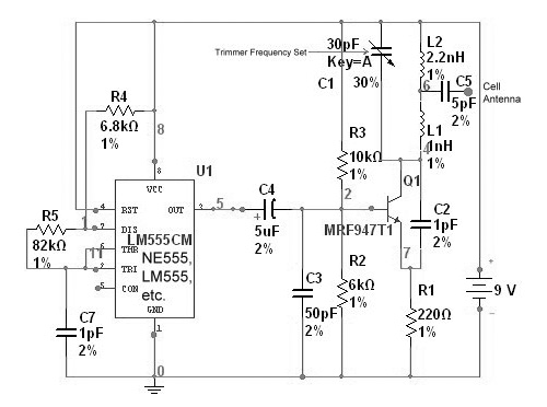
The circuit is based on the NE555 timer, functioning as a simple noise maker, with its output connected to a single transistor oscillator. This oscillator is designed to operate within a frequency range of 800 MHz to 2 GHz,...
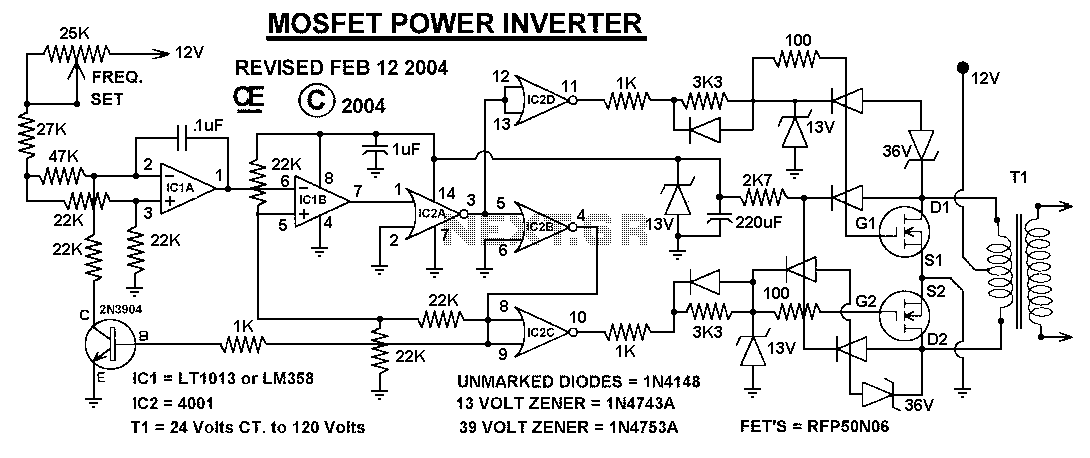
This power inverter circuit provides a stable square wave output voltage. The frequency of operation is set by a potentiometer and is typically adjusted to 60 Hz. Various off-the-shelf transformers can be utilized, or custom-wound transformers can be created...
An FM tracer was developed using the LM3909 integrated circuit (IC) along with several supporting components. This 1.5V FM tracker serves as an indicator of revenue sources by emitting a signal through an LED. The FM tracking circuit operates...
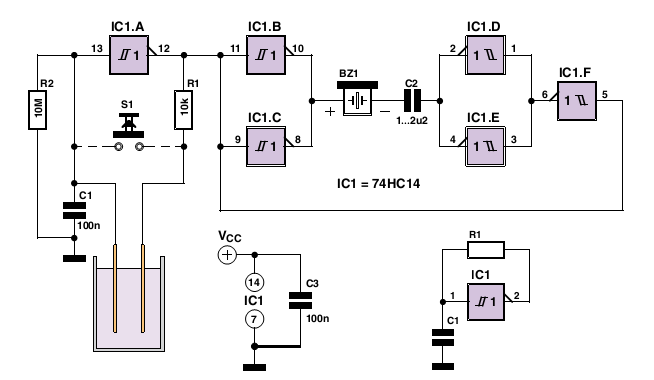
The LM1830 fluid detector integrated circuit (IC) from National Semiconductor is designed to detect the presence of fluids using a probe. This chip requires a relatively high supply voltage and is not the most power-efficient option. It is also...
A few modifications have been made to the dead band and pulse stretcher resistors, and the position feedback potentiometer has been altered to function as a "zero the speed" or "center your transmitter sticks." Additionally, a traditional PNP-NPN H-bridge...