
Astable flip-flop with starter

One precaution to note is to avoid using phenolic or printed circuit boards for this circuit when aiming for slow sequencing, as they tend to exhibit excessive leakage.
The circuit utilizes a pair of non-zener MOSPOWER transistors, which serve as the primary switching elements. These transistors are chosen for their high input impedance and low power consumption. The configuration allows for efficient control of the LEDs, which provide visual indication of the sequential flashing.
The RC circuit, consisting of a resistor and capacitor, determines the timing characteristics of the flasher. The resistor sets the charge and discharge rates of the capacitor, which in turn controls the timing of the LED flashes. By adjusting the values of the resistor (R) and capacitor (C), the timing can be fine-tuned to achieve the desired flash duration, ranging from brief moments to extended periods.
The use of MOSFETs is particularly advantageous due to their high input impedance, which minimizes the current draw from the preceding stages of the circuit. This feature allows for long sequencing times without significant power loss or the need for frequent recharging of the timing capacitor.
It is important to consider the choice of materials in the construction of the circuit. The recommendation against using phenolic or printed circuit boards is critical when slow sequencing is desired, as these materials can introduce leakage currents that adversely affect the timing performance. Instead, using materials with lower leakage characteristics, such as fiberglass or other non-conductive substrates, will help maintain the integrity of the timing circuit.
In summary, this sequential flasher circuit is a simple yet effective design that leverages the properties of non-zener MOSPOWER transistors and an RC timing network to create a versatile flashing LED application. Proper component selection and board material considerations are essential for optimal performance and reliability.A pair of non-zenered MOSPOWER transistors, a pair of LEDs and a simple RC circuit make an easy sequential flasher with almost "unlimited sequencing time—from momentary to several seconds. The infinite input resistance of the MOSFET gate allows for very long sequencing times that are impossible when using bipolars.
One precaution, though, don't wire your circuit using phenolic or printed circuit boards when looking for slow sequencing (they exhibit too much leakage!).
Related Circuits
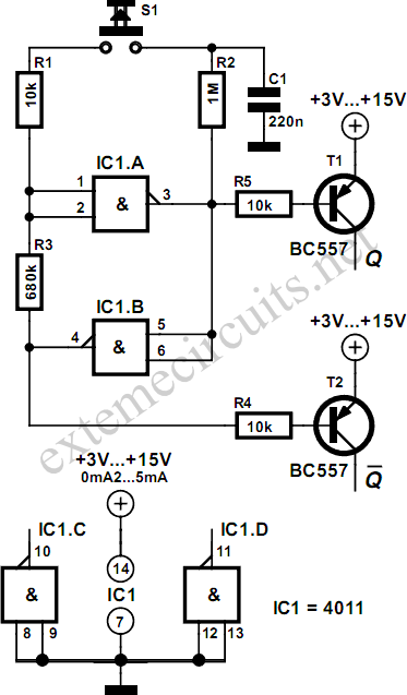
Using just two NAND or inverter gates, it is possible to build a D-type (or toggle) flip-flop with a push-button input. At power-up, the output of gate N2 is at a logical 1, ensuring that transistor T2 is switched...
To achieve a lower parts count than the two-transistor multivibrators, two LEDs can be alternately flashed using a 555 integrated circuit configured as illustrated in Schematic 2. A combination of a 2.2kΩ and a 47kΩ resistor is used to...
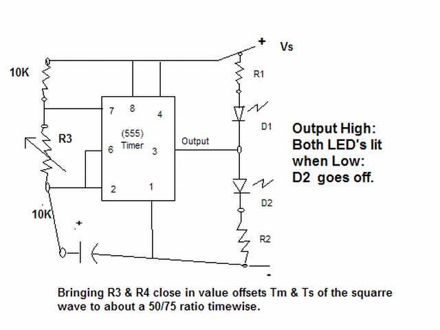
The output signal is configured to go high for approximately 0.5 seconds and then low for around 1.33 seconds. However, there is an issue present. The circuit in question likely employs a timing mechanism to achieve the specified output signal...
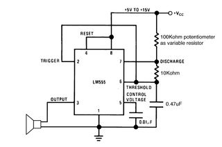
Setting the 555 timer in astable mode results in a continuous series of output pulses. The 555 timer IC, when configured in astable mode, operates as an oscillator, generating a square wave output. This configuration does not require any...

This free-running square-wave oscillator utilizes two NPN transistors. The output frequency is approximately 300 Hz with the specified component values. The circuit operates as a basic oscillator, generating a square wave output through the interaction of two NPN transistors. The...
Simulation schematic for an astable multivibrator. Parameters: Vcc = 24V, Vol = 1V, Voh = 21V. The power supply is Vcc, with connections from Vcc to ground. The time constant is determined by R1 and the capacitor C1, where...