
SAA1042 stepper motor control circuit
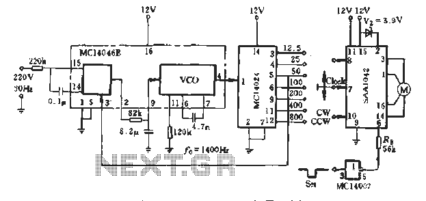
The SAA1042 stepper motor driver operates with a supply voltage of 12V, making it suitable for applications requiring precise control of motor positioning. The selection of a 200mA phase winding current indicates that the motor is designed to operate efficiently at this current level, ensuring optimal performance while minimizing power consumption and heat generation.
The resistor RE, valued at 56kΩ, plays a crucial role in setting the appropriate biasing conditions for the driver circuit, ensuring stable operation and preventing excessive current draw that could lead to overheating or damage. The integration of the NAND gate MC14007 facilitates logic operations essential for controlling the stepper motor's direction and stepping sequence.
The clock signal, generated by the MC14046 and MC14024 PLL frequency synthesizer, is vital for the timing of the stepper motor's operation. By producing a frequency range of 12.5 to 500Hz, the system allows for a variety of stepping speeds, enabling users to select from seven distinct gear ratios. This flexibility is particularly beneficial in applications requiring different levels of torque and speed, enhancing the overall versatility of the stepper motor system.
The design exemplifies a well-integrated approach to controlling stepper motors, utilizing standard components to achieve reliable and efficient motor control in various applications, from robotics to automated machinery.A typical application example shown, SAA1042 12V stepper drive motivation, phase winding current is taken as 200mA. Choose from the RB Figure 5-10, taking RE = 56kfl. It is connected to the output of NAND gate MC14007. Figure 5-9 clock by MC14046 and MC14024 PLL frequency synthesizer composition produced. Stepping clock in 12. 5- SOOHz carve seven gear selection.
Related Circuits
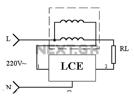
The circuit illustrated in Figure 3-2 features a loop reactor governor that incorporates a series reactor. The reactor can be constructed using a TV choke and is designed to be approximately 3mm in height. It utilizes a strength wire...
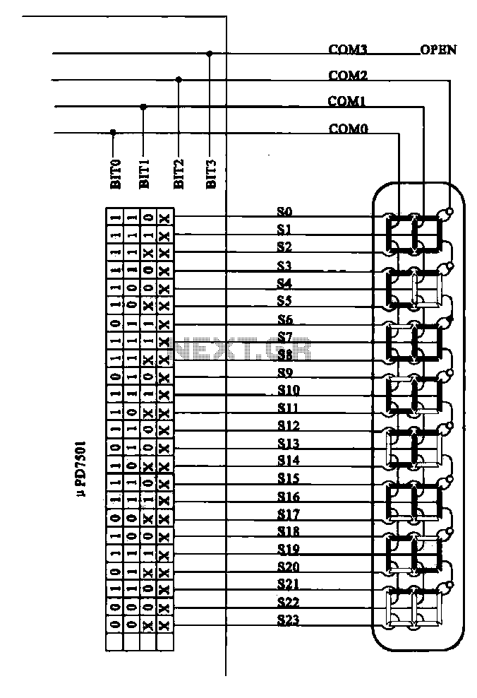
Examples of the structure of several liquid crystal display drive circuit CPU tubes. Liquid crystal display (LCD) drive circuits play a critical role in controlling the operation of LCD panels, which are widely used in various electronic devices. These circuits...
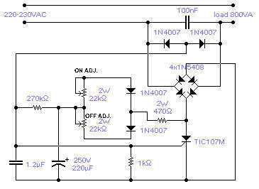
The circuit shown will switch on and off a resistive or inductive load up to 800VA with the possibility to adjust both the on and off period. Switching takes place during the zero crossing of the sine wave. The...
This is an application circuit of the device as illustrated in principle. In the meter, the voltage and current coils are connected to the power line, regardless of whether a load is connected. The voltage coil consistently draws power,...
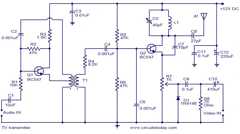
A simple two-transistor TV transmitter circuit that operates from 12V. It is compatible with PAL B and PAL G systems. The described circuit utilizes two transistors to create a basic television transmission system capable of operating on a 12V power...
This project was completed successfully, achieving the desired frequency and strength. For assistance, please reach out for support in resolving any issues. The project involves the design and implementation of an electronic circuit that operates at a specified frequency and...