
building vu meter

A basic understanding of electronics is possessed, with qualifications including an A* in GCSE Electronics and recent AS-level exams completed. Test equipment and soldering tools are available. A pre-made kit is desired, but if unavailable, a custom circuit can be designed and tested using Circuit Wizard. Depending on the signal source, it is necessary to attenuate the signal to a usable level and run it through a series of Band Pass Filters. Following this, the filtered signals should be directed into power circuits capable of driving the required number of LEDs. There is some confusion regarding the distinction between frequency-oriented and sound-level-oriented links. Initially, the focus was on frequency, as terms like low bass, mid bass, and high bass were mentioned. However, it is uncertain if these refer to low, mid, and high-level signals, suggesting a VU meter that displays signal level. Clarification is needed from the original poster regarding whether the intent is to block out the sound spectrum by frequency or to create a VU meter based solely on signal level.
The links provided in post #5 direct to VU meter kits, with each level designed to activate one LED. To drive multiple LEDs, additional power is required, presenting a separate challenge. The video in post #4 concludes with links to various LED VU Meter videos, which may provide helpful insights. Numerous YouTube videos are available for reference, and contacting creators for more information is encouraged. Utilizing acrylic blocks can enhance LED brightness, presenting a straightforward solution. The objective is to connect the meters to a music input that is heavily bass-oriented, aiming for maximum meter response during loud bass sections. If the design proves too complex, a simpler frequency-based VU meter may be considered. It is emphasized that a VU meter measures Volume Units, which is not frequency-dependent, as previously noted in earlier discussions. The instrument's purpose is to display levels at different frequencies.
To create an effective LED VU meter circuit based on the outlined requirements, the following considerations should be taken into account:
1. **Signal Amplification**: A suitable operational amplifier circuit should be employed to boost the output signal from the iPod's headphone jack. This can be achieved using a non-inverting amplifier configuration, which will ensure that the output signal maintains the same phase as the input while increasing its amplitude.
2. **Signal Attenuation**: If the input signal is too high, a voltage divider can be implemented to attenuate the signal to a safe level before amplification. This ensures that the operational amplifier operates within its linear range.
3. **Band Pass Filters**: Implementing multiple band-pass filter circuits will allow for the selective amplification of specific frequency ranges. Each filter can be tuned to target different frequency bands, such as low, mid, and high bass, enhancing the responsiveness of the VU meter to various audio signals.
4. **LED Driver Circuit**: A transistor-based driver circuit can be used to control the LEDs. This circuit should be capable of handling the current requirements of the LEDs, allowing for multiple LEDs to be driven simultaneously. The output from the band-pass filters can be fed into the base of the transistors, allowing them to turn on and off in response to the audio signal.
5. **Calibration and Testing**: After assembling the circuit, it is essential to calibrate the response of the LEDs to ensure they accurately reflect the audio levels. This may involve adjusting the gain of the operational amplifiers and the thresholds of the LED drivers.
6. **Physical Design**: The final design should consider the arrangement of LEDs and the use of acrylic blocks to diffuse the light effectively, creating an aesthetically pleasing display that responds dynamically to the music input.
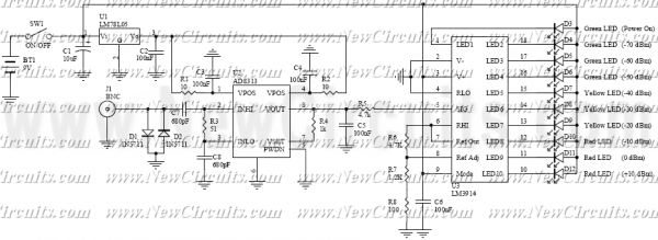
By following these guidelines, a custom LED VU meter can be constructed that meets the desired specifications and effectively visualizes audio levels in real time.Need to amplify the output of the iPod`s headphone jack would not be enough to provide the chip with a large enough signal to respond to, but this was because I had been researching three different chips. The LM3914 is a linearly calibrated device, so its output will change one-per-volt of the input. This could be a problem for low-voltage inputs like my iPod headphone jack - they would need to be amplified.
The LM3915 is a logarithmically calibrated chip, where the input exponentially alters the LED output. This is much more useful for me, as the top LEDs of the meters will respond well to the loud peaks of my music.
The LM3916 is a more technical chip, and less useful for what I want, as it is calibrated by the decibels of the input. I am not so sure how this is calculated or interpreted by the chip, but here is another crude diagram: I have an A* GCSE qualification in Electronics, and I have *just* taken my exams for AS-level Electronics.
I have test equipment at home and soldering irons etc. I would like to buy a pre-made kit but if that`s not possible i am able to create my own and test on Circuit Wizard. Depending on the source of the signal, you need to attenuate the signal down to a useable level, then run it through a series of Band Pass Filters, then those Band Pass circuits into a series of power circuits sufficient to drive as many LEDs are you need to get the job done.
I was equally confused which is why I posted both frequency oriented links and sound level oriented links. My initial reactions was Frequency oriented, as he says low bass, mid bass, and high bass. But, I wonder if he doesn`t simply mean low level, mid level, and high level signals, implying that this is a VU meter purely to display signal level.
So the original poster needs to clear that up. Is he trying to block out the sound spectrum by frequency and display it, as is seen in my first set of videos. Or does he truly mean a VU meter, which is simply signal level based The last link in post #5 are to VU meter kids.
They each level is meant to drive ONE LED. If you want to drive banks of LEDs, then you are going to need more power to drive them, which brings up a separate issue. Also notice when the video on Post #4 plays to the end, it then links to a wide range of videos of similar types of LED VU Meters.
There are countless videos on YouTube that can help you, and if you find a design that appeals to you, and you have a YouTube account, you can contact that person for more information. Also, notice you can get a lot of light from just one or two LED`s using the Acrylic blocks. That might be the simplest way. Simply find a source of Acrylic, cut the blocks to size, and combine it with a standard LED VU meter kit (links already provided).
The meters will have my music input to them, which is extremely bass-oriented. There are sections where there is loud bass and I want the meters to be at maximum at that point. If this is too complex, then I will settle with a simpler VU meter, which just registers frequency. I am not totally sure if i am using the right language here, i hope i have answered your questions though. That last video you linked is exactly the kind of thing i want to build, hopefully with as sleek looks.
The problem is that the links provided in the description of that video are in polish and the circuit diagrams are not annotated. I am confused as to their purpose and usage. The meters will have my music input to them, which is extremely bass-oriented. There are sections where there is loud bass and I want the meters to be at maximum at that point. If this is too complex, then I will settle with a simpler VU meter, which just registers frequency. No, A VU meter measure Volume Units - is it not frequency dependent. This has already been said in earler replies (did you read them ). The instrument that displays the levels at different frequencies 🔗 External reference
Related Circuits
A tachometer can be constructed using the TC9400 in frequency-to-voltage (F/V) mode to convert frequency information (RPM) into a linearly proportional voltage. This voltage can then be compared to one of several comparators (in this example, using eight). The...
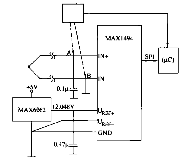
The circuit consists of the MAX1494 and a thermocouple temperature measurement system. The MAX1494 is terminated at 1N GND 5-32. An external temperature sensor, such as the DS75, can be utilized for junction temperature compensation. The MAX1494 employs an...
RF Signal Strength Meter circuits are popular RF measurement devices. This circuit is one of the simplest but very useful circuits that satisfies your desired accuracy. The heart of measurement is high accuracy but easy to use Logarithmic Detector...

The thermistor RT, along with resistors R1, R2, R3, and variable resistor RP1, creates a temperature measurement bridge. At a temperature of 20°C, the configuration of R1, R3, and the adjustment of RP1 enables the bridge to maintain balance....
The Car shows the distance a train travels on a 5 digit LCD display. The distance is indicated down to 1/100th of a mile (about the length of a 50 foot car) with an accuracy of approximately plus 2...
The input stage of this voltmeter circuit utilizes an operational amplifier and diode feedback to create a linear peak value rectifier circuit. A partial pressure isolation through resistors R1 and R2 directs the signal to a dual multi-channel BCD...