
CCD Array Reader Project

The CCD Array Reader circuit utilizes the TC102-1 CCD Linear Image Sensor, which is designed for capturing linear images with high fidelity. The sensor operates by converting incident light into an electrical charge, which is then processed into a digital signal. The circuit is structured to continuously read the output from the CCD sensor, which is inherently analog, and convert it into a digital format suitable for further processing.
The primary components of the circuit include the TC102-1 CCD sensor, an operational amplifier for signal conditioning, an analog-to-digital converter (ADC) to digitize the analog output, and a microcontroller or FPGA to manage data acquisition and communication with the PC. The operational amplifier is configured to provide the necessary gain and filtering to ensure that the signal fed into the ADC is within the optimal range for conversion.
The output from the TC102-1 is typically a parallel data stream, which requires careful timing and synchronization to ensure that the data is accurately captured. The microcontroller or FPGA is programmed to control the readout timing, ensuring that each pixel's data is sampled correctly and in sequence. The data is then sent to the PC via a suitable communication interface, such as USB or serial, where it can be visualized using a custom software application.
Power supply considerations are also critical in this design. The CCD sensor and associated circuitry require stable voltage levels, typically around 5V, with appropriate decoupling capacitors to minimize noise and ensure stable operation. Additionally, the layout of the PCB must be carefully designed to minimize interference and maintain signal integrity, particularly in the analog sections of the circuit.
Overall, the CCD Array Reader project represents a practical application of CCD technology, enabling the capture and analysis of linear images in a straightforward and efficient manner.The CCD Array Reader project began with a free sample of the Texas Instruments TC102-1 CCD Linear Image Sensor and its rather terse data sheet. The TC102-1 provides virtually no support circuitry, only the raw CCD (with a few special pixels) and a simple output buffer.
The board shown below was designed to continously scan the TC102-1 and output a stream of digital data in parallel format. A PC computer displays the data graphically using a simple program. 🔗 External reference
Related Circuits
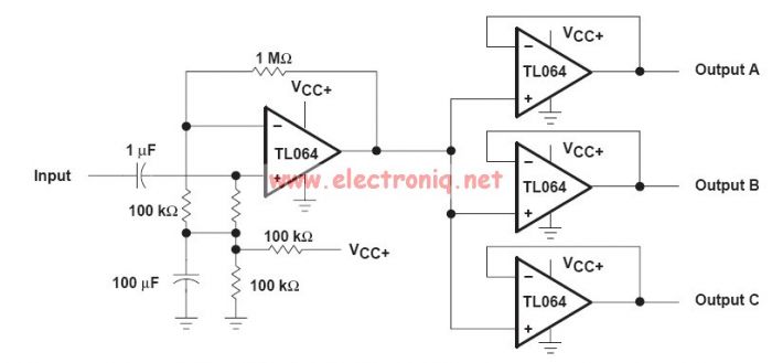
This audio distribution electronic project circuit diagram is designed using the TL064 or TL06 operational amplifiers and some other common electronic parts. The audio distribution circuit utilizes TL064 or TL06 operational amplifiers, which are quad op-amps known for their low...
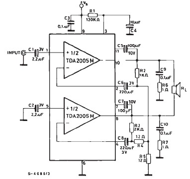
TDA2005 car audio amplifier circuit diagram electronic project using few external electronic parts The TDA2005 is a robust integrated circuit designed for audio amplification in automotive applications. This circuit diagram outlines a project for a car audio amplifier that utilizes...
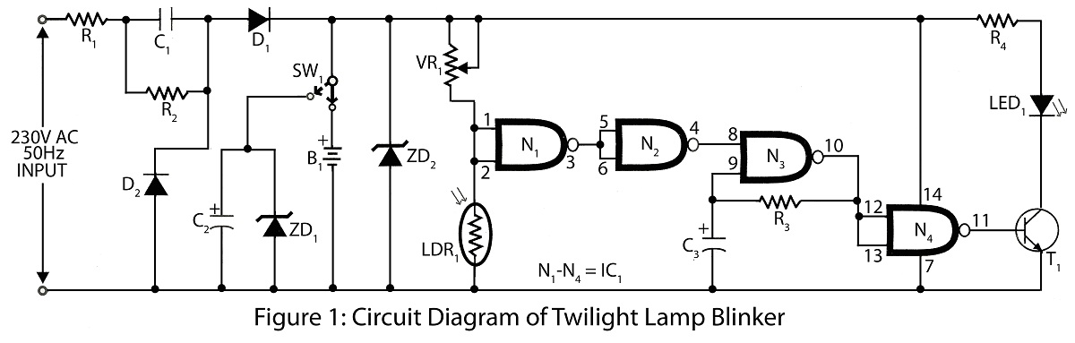
Twilight Lamp Blinker circuit can be constructed using a Light Dependent Resistor (LDR) and a single integrated circuit (IC). The circuit diagram includes a parts list for various projects utilizing the LDR and additional components. The Twilight Lamp Blinker circuit operates...
Irisys offers a selection of five thermal imaging temperature sensors that utilize a 16G—16 pixel array, providing various options for temperature range, accuracy, and measurement angle. The IRI 1041, IRI 1051, and IRI 1061 models are identical to the...
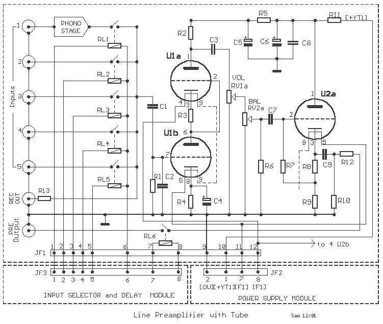
The interest in tube circuits remains significant. Therefore, I will provide a comprehensive circuit of a preamplifier that is sufficiently detailed. It is primarily composed of the main preamplifier department, the input selector department, application voltage delay, and the connection...
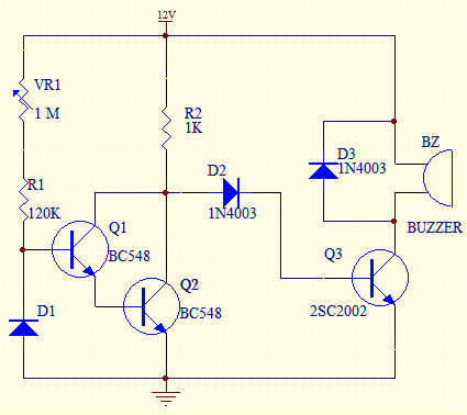
This temperature switch utilizes several discrete components to activate a buzzer when the ambient temperature rises. It is suitable for use as a straightforward fire alarm indicator. The temperature switch circuit is designed to monitor environmental temperature changes and provide...