
CMOS Pocketable Timekeeper

The CMOS Pocketable Timekeeper circuit utilizes complementary metal-oxide-semiconductor (CMOS) technology, which is known for its low power consumption and high noise immunity. The design typically includes a crystal oscillator to provide a stable clock signal, which is essential for accurate timekeeping. The oscillator's frequency is usually set to 32.768 kHz, a standard frequency for timekeeping applications, allowing the circuit to maintain precise time over extended periods.
The circuit may incorporate a microcontroller or a dedicated timer IC, which processes the clock signal and manages timekeeping functions. This component is responsible for counting the clock pulses and converting them into human-readable time formats, such as hours, minutes, and seconds. Additionally, the microcontroller may include features like an alarm function, timer settings, and user interface controls, such as buttons for adjusting the time.
Power management is a critical aspect of the design, especially for a pocket-sized device. The circuit typically operates on a low-voltage power supply, often using a coin-cell battery. This design choice enhances portability while ensuring that the device can function for extended periods without frequent battery replacements.
The output of the timekeeping circuit can be displayed on a small LCD or LED screen, showcasing the time in a clear and readable format. The schematic may also include additional components such as resistors, capacitors, and diodes to filter noise and stabilize the power supply, ensuring reliable operation of the timekeeping function.
In summary, the CMOS Pocketable Timekeeper circuit diagram represents a sophisticated yet compact design that effectively combines various electronic components to create an efficient and portable timekeeping solution suitable for a wide range of applications.CMOS Pocketable Timekeeper is pocket size time circuit circuit diagram of CMOS Pocketable Timekeeper and various other timer project advanced timer and electronics project. 🔗 External reference
Related Circuits

This circuit utilizes a 4049 integrated circuit (IC) to control a 2N2222 switching transistor. The transistor, in turn, drives a piezo transducer known as crystal 1. The circuit design begins with the 4049 IC, which is a hex inverter capable...

The circuit below uses a CMOS dual D flip flop (CD4013) to toggle a relay or other load with a momentary push button. Several push buttons can be wired in parallel to control the relay from multiple locations. A...
This is an astable multivibrator (oscillator) circuit utilizing a CMOS inverter. The circuit employs the CD4007 or MC14007 components. It operates within a frequency range of... The astable multivibrator circuit is designed to generate a continuous square wave output without...
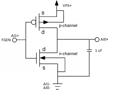
Using measured threshold voltage and Ids-Vds curves, the performance of first-order MOSFET theory can be evaluated in real devices, allowing for an understanding of the limitations of first-order theoretical MOSFET equations. The MOSFETs employed in this experiment are from...
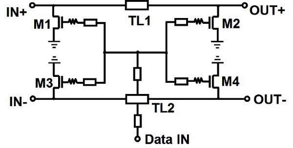
An edge combiner utilizing MOSFETs C and D is designed to generate a 16 ps pulse. The center frequency varies as a function of the NMOS width (Wser) relative to the inverter width (Winv). Figure 12 illustrates the transmitted,...
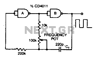
Adjusting the 100 K ohm potentiometer modifies the discharge rate of capacitor Ct, thereby affecting the output frequency. A square wave output is produced. The maximum frequency achievable with CMOS technology is constrained to 2 MHz. The circuit described involves...