
IC Encoder Chip
The implementation of a simple function in a PLD or FPGA offers flexibility and adaptability in electronic design. The choice of using a PLD or FPGA depends on the complexity of the function, the available resources, and the overall design requirements. When considering a small PLD, careful analysis is necessary to ensure that the I/O pin allocation does not become a limiting factor. Each I/O pin consumed reduces the capability to add further functionalities, which could lead to inefficiencies in the design process.
In cases where the function is straightforward, utilizing a less expensive alternative may be more beneficial, provided it meets the performance criteria. However, if the design anticipates future expansions or modifications, a PLD can be a strategic choice. It allows for reprogramming and adjustments without the need to redesign the entire circuit, thus offering long-term value.
When designing with PLDs, it is essential to create a schematic that clearly outlines the connections between the PLD and other components in the circuit. This includes defining the power supply connections, ground connections, and the routing of I/O pins to external devices. Additionally, the schematic should illustrate any necessary logic gates, flip-flops, or multiplexers that may be required to implement the function effectively.
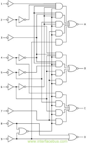
In conclusion, while the initial implementation of a simple function in a PLD may seem straightforward, careful consideration must be given to resource management, cost implications, and future scalability. The ability to replace multiple glue logic ICs with a single PLD can lead to a more streamlined and efficient design, making it a valuable tool in modern electronic engineering.This is not a complex function and could be easily coded into a PLD or FPGA. However implementing this function into a small PLD might just use up most of the chip`s I/O pins and defeat the purpose of the PLD. That is; spending more for the PLD, than using most of it up implementing a much cheaper part. However it could be possible to implement th is function in a PLD and have space and I/O pins left over to implement additions functions, and using a PLD to replace one than one glue logic IC. 🔗 External reference
Related Circuits
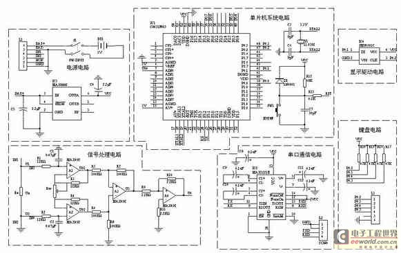
A one-chip computer has been utilized to design this survey meter, which directly displays the measured resistance on an LCD screen. The measurement range extends from 0 to 9999 kΩ, and the device can simultaneously store the measured data,...
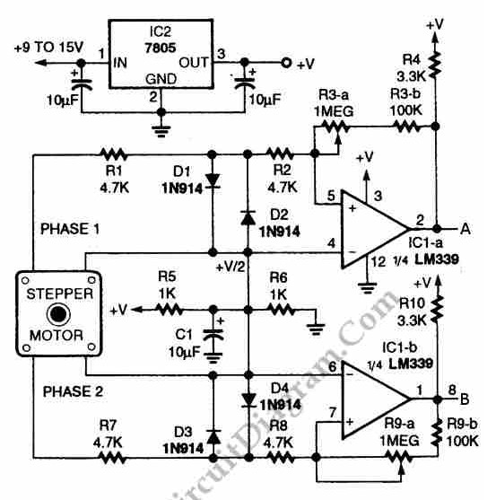
The circuit illustrated in the schematic diagram below allows for the visualization of the direction and shaft rotation of a stepper motor on an LED display. Instead of utilizing a digital rotation encoder as an input, this circuit employs...
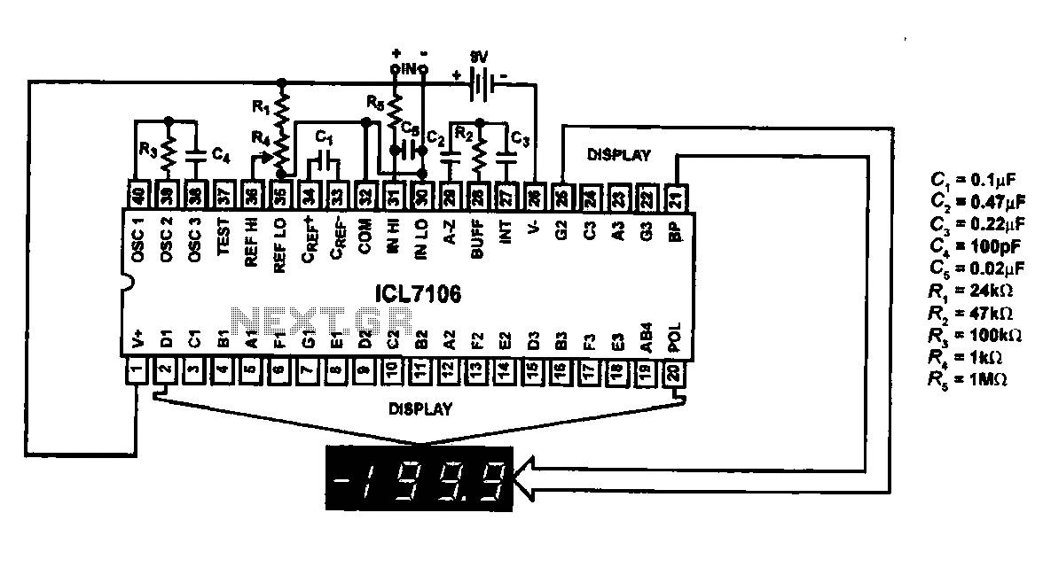
This circuit utilizes the ICL7106 / ICL7107 chip to drive a liquid crystal display (LCD). In this configuration, the ICL7106 / ICL7107 functions as a signal measurement and analog-to-digital (A/D) converter. It detects an analog input signal, amplifies it,...
The circuit is a simple op-amp but with two diodes (the transistor b-e junctions in the feedback to split the feedback for positive and negative outputs. On positive output from the stepper coil the top transistor turns on, on...
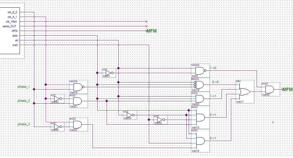
An MFM Encoder operates based on the principles of time shifting and phase shifting. This technique relies on the transmission frequency, with MFM signals generated in conjunction with double the transmission frequency. Further information regarding MFM can be found...
The MT8870 is a complete DTMF receiver that integrates both the band-split filter and digital decoder functions. The filter section employs switched capacitor techniques for high and low group filters, while the decoder utilizes digital counting methods to detect...