Latching Current Limiter
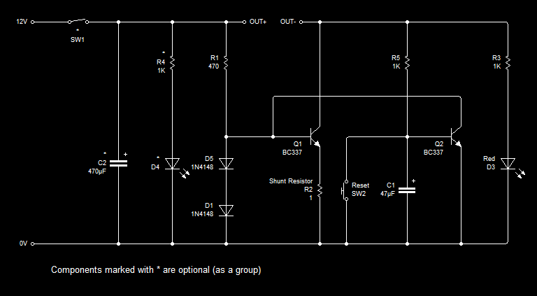
This entry describes a modification of a current limiter circuit originally created by Ron J. The original circuit functions as intended; however, a need arose to disconnect the load immediately after the maximum current threshold was reached, effectively creating a resettable fuse. When the current exceeds approximately 500 mA, the circuit disconnects the load. Even if the load attempts to draw less than 500 mA afterwards, it remains disconnected until the reset button is pressed or the load is physically reconnected. A BC337 transistor was selected for this application, although any general-purpose or medium-power transistor that can handle at least 150 mW should suffice, particularly in worst-case scenarios where the reset button may be stuck and Q1 could fail. All resistors are rated at 1/4W with a tolerance of 5%, while the shunt resistor should be rated at least 1/2W with a tolerance of 1%. The latching behavior of the circuit is facilitated by Q2, which pulls the base of Q1 to ground, effectively turning off the transistor. Once Q1 is off, the OUT- lead is no longer connected to ground, allowing the LED to conduct. Resistor R5 provides sufficient base current for Q2 to remain active. Discharging the capacitor through the reset button unlatches the circuit; when R5 is grounded, Q2 no longer receives current, allowing Q1 to conduct once again.
This circuit modification serves as a resettable fuse that automatically disconnects the load when the current exceeds a preset limit, enhancing the protection of connected components. The circuit operates by utilizing a transistor-based latching mechanism, where Q1 controls the load and Q2 manages the state of Q1. The design incorporates a reset feature, which is crucial for restoring functionality after a fault condition.
To construct this circuit, the following components are required: a BC337 transistor or equivalent, a second transistor for latching, resistors with specified power ratings and tolerances, and a capacitor for timing purposes. The reset button should be a momentary switch that allows the user to discharge the capacitor, thereby resetting the state of the circuit.
The configuration of the circuit should ensure that the base of Q1 is driven appropriately to control the load current. The shunt resistor must be placed in series with the load to monitor the current flow accurately. The values of the resistors must be chosen to provide the correct biasing for Q2 while ensuring that the circuit remains stable during operation.
Overall, this modification provides a reliable method for protecting circuits from overcurrent conditions while allowing for easy reset and restoration of normal operation. Proper testing and validation should be conducted to ensure the circuit performs as expected under various load conditions.As my first electronics-related entry, I would like to share a modification of the current limiter add-on by Ron J. The original circuit works as advertised, however I needed to disconnect the load immediately after the maximum current was reached, what I needed was pretty much a resettable fuse.
Should you attempt to draw over ~500mA, the ci rcuit will disconnect the load. Even if the load no longer attempts to draw half an amp, it will remain disconnected until the reset button is hit or the load is physically reconnected. BC337 was chosen in this case but any general purpose or medium power transistor will suffice as long as it can handle at least ~150mW (worst case scenario someone glued the reset button and Q1 blows).
All resistors 1/4W 5%, the shunt resistor should be at least 1/2W and 1%. The latching behavior is possible thanks to Q2. It`s job is to pull the base of Q1 to ground, this effectively allows us to turn the transistor off. Now that it ceased to conduct, the OUT- lead is no longer tied to ground, therefore the LED is allowed to conduct. R5 will now provide enough base current for Q2 to remain active. Discharging the capacitor through the reset button unlatches the circuit. ie. Now that R5 is tied to ground, the base of Q2 no longer receives any current and therefore Q1 conducts again.
If you find any mistakes or would like to enhance the circuit, feel free to do so! Keep in mind that I`ve successfullybuilt and tested this; otherwise I wouldn`t be posting it 🔗 External reference
