The K9AY receiving loop antenna
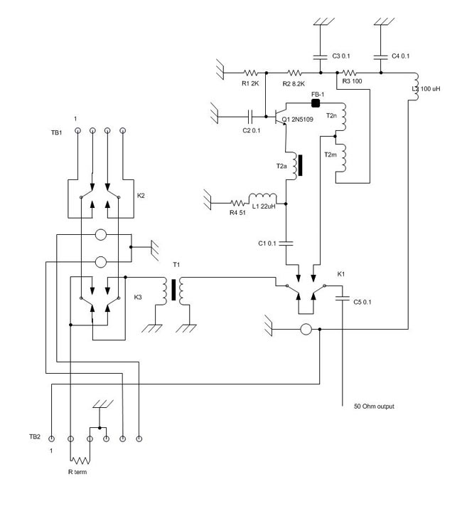
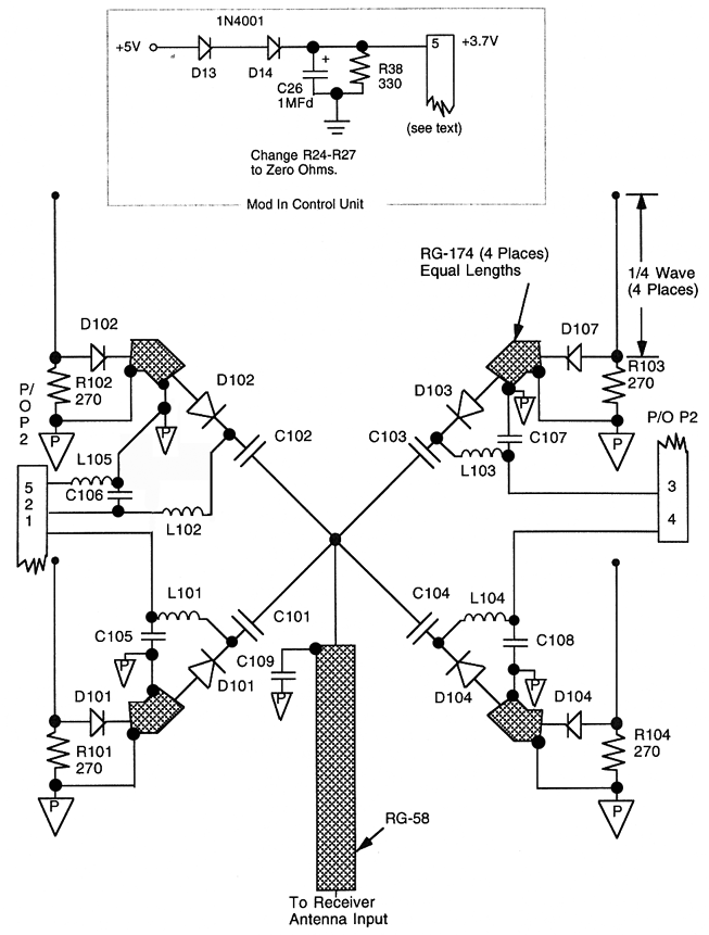
A K9AY antenna system and controller has been designed with the intention of creating a more effective unit at a lower cost compared to commercially available versions. The K9AY antenna features a steerable null, maintaining a gain close to unity, except for the terminated side of the loop, which exhibits a deep null. The configuration allows for switching between loops and terminations using a relay system, which is particularly beneficial for medium wave (MW) and short wave (SW) listening, as it helps mitigate interference from co-channel stations. The antenna has proven successful in enhancing reception, especially in the AM band. A solid ground connection is essential for optimal performance, and it is recommended to install two radials beneath each loop to ensure consistent ground conductivity, thus stabilizing the termination resistance (Rterm) across different bands. Additionally, a low-noise preamplifier is proposed to be placed directly at the antenna to counteract transmission line losses and losses from a four-port passive receiver coupler. A Norton preamplifier design utilizing a single active device, the 2N5109 BJT, is suggested. Typically, this preamp remains switched off, but it can provide an additional 10 dB of gain when needed, significantly improving reception quality.
The K9AY antenna system is characterized by its unique configuration that allows for effective null steering, making it an advantageous choice for amateur radio operators and enthusiasts engaged in MW and SW listening. The antenna consists of two loops, each capable of being terminated to create a null in specific directions. This feature is particularly useful in crowded frequency environments where multiple stations may interfere with one another. The relay switching mechanism enables the user to dynamically alter the antenna's response to incoming signals, enhancing the ability to isolate desired transmissions from unwanted noise.
Grounding plays a critical role in the performance of the K9AY antenna. The recommendation to install radials beneath each loop is essential for maintaining low resistance and consistent ground conductivity. This setup helps to stabilize the termination resistance, ensuring that the antenna maintains its designed characteristics across different frequency bands. The use of radials not only improves the efficiency of the antenna but also contributes to overall signal clarity and reception quality.
The inclusion of a low-noise preamplifier at the antenna feed point is a strategic enhancement to the K9AY system. By addressing transmission line losses and losses incurred through passive components, the preamp improves the overall signal-to-noise ratio. The choice of a Norton preamp design with the 2N5109 BJT is particularly effective due to its simplicity and reliability. The preamp operates in a manner that allows it to remain inactive during normal conditions, thus preserving the integrity of the signal path. However, when additional gain is required, the preamp can be activated to provide a substantial boost, thereby improving the ability to receive weak signals that might otherwise be lost in the noise floor.
Overall, the K9AY antenna system, with its steerable null capability, robust grounding recommendations, and integrated preamplification, represents a well-conceived solution for radio enthusiasts seeking to optimize their reception capabilities across a range of frequencies.I decided to make my own K9AY antenna system and controller. Basically, after looking at the currently available commercial version, I figured I could make a better unit for less money and be happy. The basis for the K9AY antenna is that it has a steerable null. The gain around the antenna is close to unity, except for the terminated side of the loop, which has a deep null.
This can be switched around using a combination of relays that change the loops and termination. This comes in very handy for MW and SW listening, when co-channel stations can create annoying interference and hetrodynes. I have had good success pulling many stations out of the muck, especially in the AM band using this antenna.
This antenna requires a good ground to work against. For optimum installations, I would recommend placing two radials under each side of the loops. This will keep the ground conductivity below the antenna fairly constant, thus the value of Rterm will remain consistent for each band. My other idea is to add a preamp right at the antenna to overcome transmission line loss and the loss from a 4 port passive receiver coupler.
Something around 10 dB, low noise (obviously), low parts count and rugged. I decided that a Norton preamp was a good design, with only one active device, a common 2N5109 BJT. Most of the time, this preamp is switched off and out of the circuit. There have been several occasions, however, where an extra 10 dB made the difference between no copy and good copy. 🔗 External reference
