
for beginners reading schematics circuit diagrams

No description available.
Related Circuits
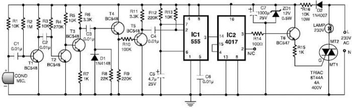
This 555 timer clap switch circuit electronic project is designed using common electronic components. The circuit operates from a distance of up to 10 meters from the microphone. The signal from the microphone is amplified by transistors T1, T2,...
This is a simple transistor tester circuit that can be utilized to test both NPN and PNP transistors. The voltage source consists of a 6V power supply, which is derived from a step-down transformer that converts 230V AC to...
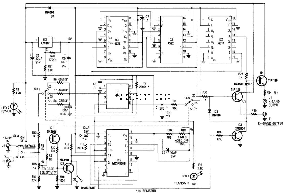
This circuit is a system designed to generate a pulsed modulation signal for a Gunn diode microwave oscillator. It features several preset speed settings (S3 a and b). A 555 timer is employed in conjunction with a frequency divider...

This is a design schematic for sensing the electromagnetic field. The circuit is built using a 741 operational amplifier (op-amp) IC. It can detect electromagnetic fields, including those from hidden wiring. A 1mH inductor is employed for sensing the...
This is a range of IF signal circuits that may be of interest to radio hobbyists and professionals alike. Transistors T1 and T2 form an astable multivibrator oscillating in the audio frequency range of 1 to 2 kHz. An...
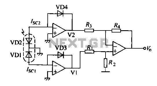
The operation of a semiconductor color sensor can be summarized as follows. The figure illustrates the spectral response curve of two photodiodes that intersect at a specific wavelength. When light of this wavelength is incident on the photodiodes, the...