
Light circuit diagram: Electromagnetic Sensor Circuit Using 741 IC

The electromagnetic field sensing circuit utilizes a 741 op-amp, which serves as the core amplification component. The circuit is designed to detect low-level electromagnetic fields, making it suitable for various applications, including electrical safety checks and monitoring electromagnetic interference.
The 1mH inductor acts as the sensing element. When exposed to an electromagnetic field, it generates a voltage proportional to the intensity of the field. This voltage is fed into the non-inverting input of the op-amp, where it is amplified. The gain of the op-amp circuit can be adjusted via the potentiometer R4, allowing for precise tuning based on the specific application and sensitivity requirements.
The output from the op-amp is connected to a pair of headphones, enabling audio feedback of the detected electromagnetic signals. This audio output can manifest as a hum or other sounds corresponding to the frequency of the electromagnetic field, providing an intuitive way for users to perceive the presence and strength of the field.
To ensure the reliability of the circuit, all electrolytic capacitors should have a voltage rating of at least 15V, which provides a safety margin for typical operational voltages. The inclusion of switch S1 allows the user to easily turn the circuit on or off, conserving battery life and preventing unnecessary exposure to electromagnetic fields when not in use.
For optimal performance, a radial type inductor is recommended for L1, as it can provide better inductance stability and lower parasitic capacitance compared to other inductor types. Overall, this circuit design offers a practical solution for sensing and analyzing electromagnetic fields in various environments.This is a design schematic to sensor the electromagnetic field. This circuit is based or built by 741 IC. This IC is an op-amp. The circuit can detect the field even hidden wrings. This is the figure of the schematic. A 1mH inductor is used for sensing the electric field. The electric field will induce a small voltage in the sensor inductor and th is induced voltage is amplified by the op amp. The headphone connect at the output of the op amp will give an audio indication of the electric field. For example, the electric field around a main transformer can be heard as a 50 Hz hum. The POT R4 can be used to adjust the gain of the amplifier. By keeping the sensor inductor near to a telephone line, you can even hear the telephone conversations.
All electrolytic capacitors must be rated at least 15V. The switch S1 can be a slide type ON/OFF switch. The POT R4 can be used to adjust the gain. It is better to have a radial type inductor for L1. 🔗 External reference
Related Circuits
Incorporate a straightforward, economical jack-sensing circuit (JACKSENSE) into a DirectDrive automotive headphone amplifier to detect when headphones are plugged into the audio jack. The implementation of a jack-sensing circuit (JACKSENSE) in a DirectDrive automotive headphone amplifier is designed to enhance...
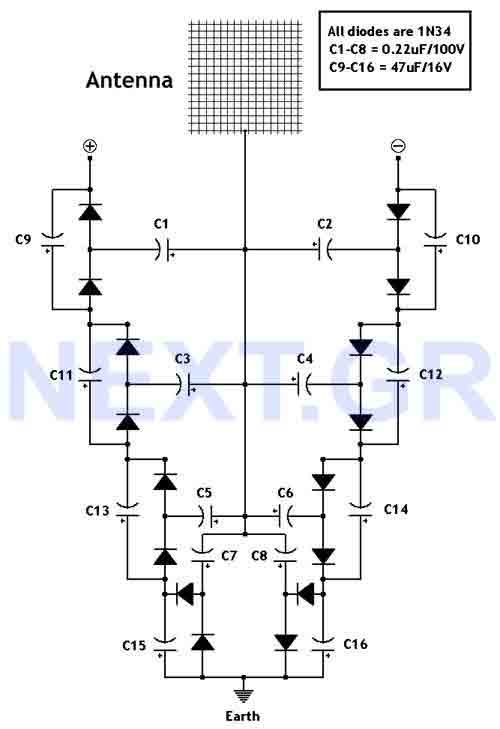
This circuit converts surrounding radio frequency waves to electric power. It can provide 40 Volts at 10 Watts indefinitely. The output power can be improved by adjusting the antenna. Placing the antenna near large metal objects increases power. The...
The Adjustable Timer circuit initiates timing upon activation. A green LED illuminates to indicate that timing is in progress. Once the designated time period elapses, the green LED turns off, the red LED activates, and an audible bleeper sounds....
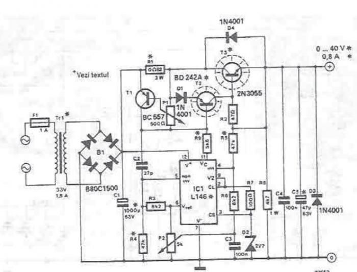
An adjustable laboratory power supply capable of providing an output voltage range from 0 to 60 volts can be constructed using the provided circuit diagram. This power supply can utilize the LM723 chip for lower voltage applications or, for...
The following circuit illustrates the use of the AD8531 integrated circuit for the automatic control of LCD panel backlighting. Features include the ability to compensate for aging effects. The AD8531 is a precision operational amplifier that is well-suited for applications...
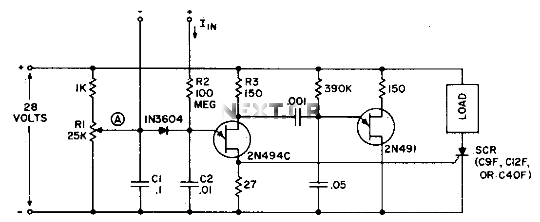
The circuit can function as a sensitive current detector or a voltage detector with high input impedance. Resistor Rl is configured so that the voltage at point (A) is V2 to a few volts below the threshold that activates...