
Clock keeps on ticking
The Ring Counter Clock operates using a combination of mechanical and electronic components to accurately track time. The central feature of the design is the use of three ring counters, which are capable of counting in their respective time units: seconds, minutes, and hours. The 1MHz crystal oscillator serves as the timing reference, generating a stable frequency that is divided down to produce a 1Hz pulse. This pulse acts as the clock signal for the ring counters.
The ring counters are interconnected in such a way that the completion of a count in one ring triggers the next ring. Specifically, when the seconds ring completes a full cycle of 60 counts, it sends a pulse to the minutes ring, prompting it to increment by one. This cascading effect continues up to the hours ring, ensuring that the clock maintains accurate time.
The use of the 2N4990 SUS in each ring section is notable for its reliability and simplicity. This component allows for the switching action required to advance the count within each ring. The design incorporates feedback from the last section of each ring to the first, creating a closed-loop system that resets the counter after reaching its maximum count.
The startup capacitor plays a crucial role in ensuring that the clock initializes correctly upon power-up. By holding the gate of the first ring section down, the capacitor ensures that the clock starts at the correct time of 12:00:00, providing a reliable starting point for operation.
Overall, this Ring Counter Clock exemplifies the ingenuity of early electronic design, showcasing the ability to create functional timekeeping devices without the reliance on modern microprocessors. Its longevity and accuracy are testaments to the quality of the engineering and materials used in its construction.I designed and built this Ring Counter Clock in 1970. The base is a 12" diameter/2" thick block of walnut from a hollowed-out gun stock blank. The back side of the base has been hollowed out to hold the circuit board. I chucked it up in a large lath and turned it inside and out. Then I drilled 120 holes for the lights and five holes in the center for controls and a time base trimmer. The copper clad board was made by making a drawing board layout on Mylar with tape dots and strips, twice the size of the board. Then a board size photo negative of the art work was used to photo print the board. This clock can maintain time of ±1 sec for months, and has been operating for 41 years, except when it was necessary to replace a bulb and when it was moved from one state to another.
I keep thinking I will replace the bulbs with LED`s some day, maybe when I run out of bulbs. Many of you may be too young to know, but in 1970 we did not have microprocessor chips to perform every electronic function known to man. We actually made circuits to perform the functions we needed, without programming. The electronics of the clock consist of a clock circuit made up of a 1MHz crystal oscillator and a TTL divider chain down to a 1Hz pulse.
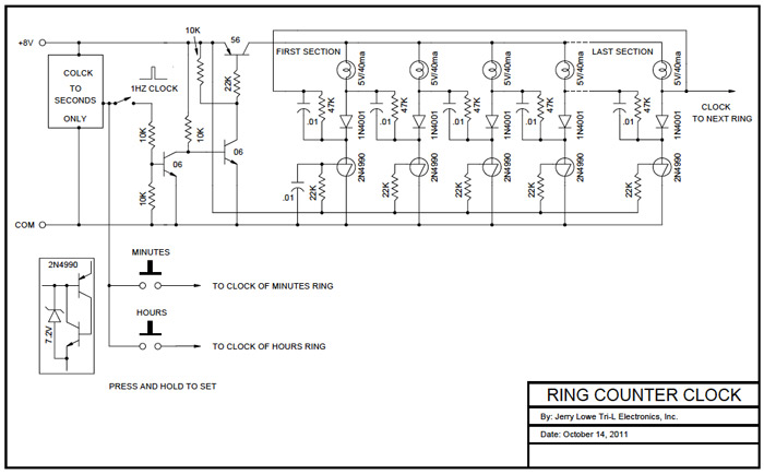
I did not show the clock circuit because there are several more simple ways to arrive at a 1Hz pulse now then how I designed this in 1970. The ring counter circuit shown in the schematic is a modified circuit of one shown in the first edition GE semiconductor data handbook.
There are three of these ring counters used in the clock: one 60 section ring for the seconds, one 60 section ring for the minutes and one 12 section ring for the hours. Each of the ring section is designed around a 2N4990 SUS (silicon unilateral switch), I believe this device is still available, if not it should be, it has many uses.
The output of the last section of the each ring returns to the first section to start the ring on "1" again. The output of the last section of the seconds ring also clocks the minutes ring. The output of the last section of the minutes ring also clocks the hours ring. When the seconds ring turns on the 60 second light it indexes the minute ring. When the minute ring turns on the 60 minute light it indexes the hour ring, and around and around it goes.
Also notice the start up capacitor on the gate of the first section of each ring. It holds the gate down when power is switched on, causing the first section of the rings to turn on for 12:00:00. 🔗 External reference
Related Circuits
This design allows for the construction of an electromagnetically impulsed pendulum clock with a 1-second beat. The prototype features a pendulum rod measuring 115 cm in length, with a bob adjusted to achieve a 1-second beat. It is suspended...
This device is a combination digital clock timer and solar panel charge controller designed to maintain a deep cycle battery from a solar panel. The timer output controls a 12-volt load for a 32-minute interval each day. The start...
U1 is a 3817 integrated circuit produced by Fairchild Corporation. It is capable of directly driving a display and can operate in both 12-hour and 24-hour formats. Additionally, it can generate a clock sound and activate radios at scheduled...
After the SCL line is high, the SDA line must be held low to indicate that the data being transmitted is legally binding. The data can only change when the SCL line is low. During the transfer of a...
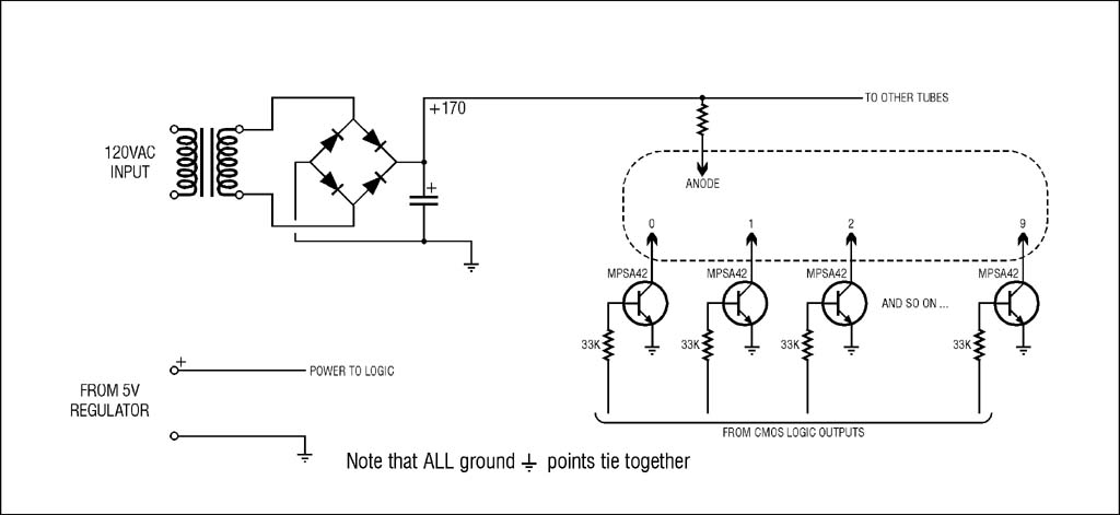
The high voltage supply will function, but for safety and to prevent accidental damage during troubleshooting with an oscilloscope, it is highly recommended to use an isolation transformer on the 120VAC input. A small 1:1 transformer rated at 30VA...
This project is a GPS-based clock that displays the current date, automatically adjusts for daylight saving time, shows current speed, maximum speed, and present heading in degrees relative to true north. The original firmware and concept were developed by...
Warning: include(partials/cookie-banner.php): Failed to open stream: Permission denied in /var/www/html/nextgr/view-circuit.php on line 713
Warning: include(): Failed opening 'partials/cookie-banner.php' for inclusion (include_path='.:/usr/share/php') in /var/www/html/nextgr/view-circuit.php on line 713