
coil coupled operation metal

The Coil Coupled Operation (CCO) Metal Detector utilizes a transformer coupled oscillator (TCO) configuration, which is integral to its functionality. The TCO consists of a primary coil and a secondary coil, where the interaction between these coils generates an oscillating signal. This signal is modulated by the presence of metallic objects in proximity to the coils, allowing for detection.
The device's reliance on a Beat Frequency Oscillator (BFO) sourced from a Medium Wave radio enhances its detection capabilities, enabling it to operate effectively across various environments. The sensitivity of the detector is significantly improved through the careful balancing of the two coils, which is crucial for distinguishing between different types of metals and minimizing false positives.
Unlike traditional Induction Balance (IB) detectors, which employ passive components, the CCO design incorporates an active receiver section within the oscillator. This active configuration allows for better signal amplification and processing, resulting in superior detection performance. Additionally, the flexible coil placement in the CCO design simplifies the setup process, making it more user-friendly than its IB counterparts.
In terms of discrimination, the CCO Metal Detector is equipped to differentiate between various metal types, which is essential for treasure hunters and archaeologists seeking specific targets. The results from experimental iterations of this design suggest that it can achieve performance levels comparable to the most advanced IB detectors available on the market, thus marking a significant advancement in metal detection technology.The metal detector shown here may well represent a new genre. At any rate, after some exposure, it is regarded as such by those who have seen it. It is based on a standard transformer coupled oscillator(TCO) - hence the name Coil Coupled Operation (CCO) Metal Detector. Although requiring a BFO (in this case provided by a Medium Wave radio), it dif fers from a typical BFO detector in that its performance far outstrips that of BFO. Also, unlike BFO, it is dependent on the balance of two coils to boostsensitivity. It also differs from IB, in that its Rx section is an active, rather than passive, component of the oscillator. Further, unlike IB, the design does not require critical placement of thecoils. As with both BFO and IB, the design provides discrimination. Experiments with different embodiments of the idea have shown that it has the potential to match the best of IB.
Happy hunting! 🔗 External reference
Related Circuits
A battery-operated Tesla coil is being developed, and assistance is needed for converting direct current (DC) to alternating current (AC) to power a high-voltage transformer. To convert DC to AC for powering a high-voltage transformer in a Tesla coil circuit,...

The circuit consists of two balanced components forming a simple Beat Frequency Oscillator (BFO) metal detector. The BFO utilizes a ready-assembled and tested circuit board with a PIC 12F675 chip at its center. This passive detector employs a detector...
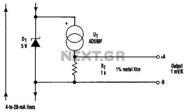
At the core of this circuit is the KTY10 temperature sensor from Siemens. This silicon sensor functions as a temperature-dependent resistor, integrated as one arm of a bridge circuit. A preset potentiometer (P1) is used to balance the bridge...
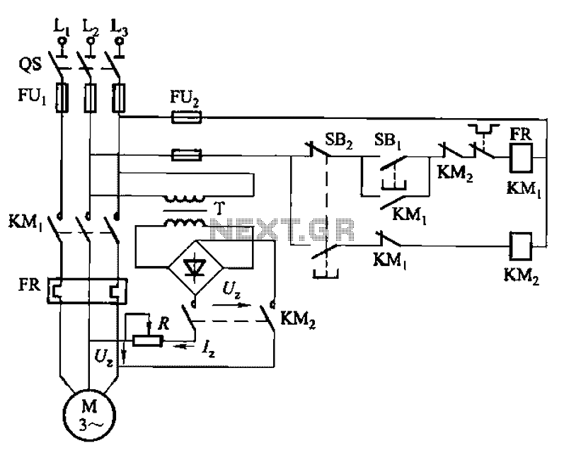
The 3133 circuit is illustrated in Figure 3-133. It features dynamic braking controlled manually via buttons in three separate lines. In part (a) of the figure, the dynamic braking DC power supply is depicted with a step-down transformer and...
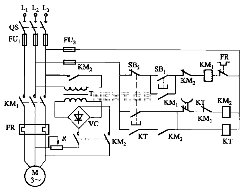
The circuit depicted in Figure 3-135 employs a time relay (KT) to determine the braking time. The circuit utilizes a time relay, which is a crucial component for controlling the duration of the braking process. The time relay KT is...
In a servo system, the current drive connection is frequently utilized. The output current (IOUT) is proportional to the input channel number (y). Using the current drive mode can mitigate issues caused by the motor's large inductance, which induces...