
8-bit parallel input serial output interface circuit

An 8 parallel input/serial output interface circuit is designed to convert multiple parallel data inputs into a single serial output stream. This type of circuit is commonly used in digital systems where data needs to be transmitted over a limited number of wires or channels.
The circuit typically consists of eight data input lines, which can be connected to various data sources, such as sensors or microcontrollers. Each input line represents one bit of data. The circuit employs a multiplexer or a shift register to facilitate the conversion of the parallel data into a serial format.
A clock signal is essential for the operation of this interface, as it synchronizes the data transfer process. The clock signal determines when the data on the input lines is sampled and shifted out serially.
In addition, control signals may be included to manage the operation of the circuit, such as enabling or disabling the data transfer or selecting specific input lines for transmission.
The output of the circuit is a single serial data line that can be connected to a microcontroller, communication interface, or any other device that requires serial data input.
This configuration allows for efficient data transmission while minimizing the number of connections required, which is particularly beneficial in applications with space constraints or where wiring complexity must be reduced.8 parallel input/serial output interface circuit as follows:
Related Circuits
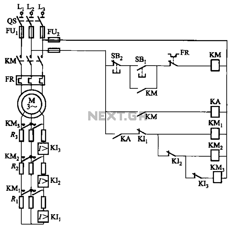
The circuit illustrated in Figure 3-161 features a first stage current detection mechanism utilizing a current relay (KI1) in series with a resistor (R1). The second stage employs another current relay (KI2) in series with a resistor (R2) for...
This modified Hartley oscillator can be utilized to attract new friends or serve as a replacement doorbell. The modified Hartley oscillator is a type of electronic oscillator that generates a continuous waveform, typically a sine wave, using an LC (inductor-capacitor)...
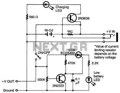
Intended for a NiCad application, this charging circuit can be used with a wide range of batteries. A low-battery detector is included, and the trip voltage is set via a 500 kΩ potentiometer. Select the resistor for the battery...
The following circuit diagram depicts a variable power supply controlled by a PIC microcontroller. An LCD display is utilized to show the actual output current and voltage values. This digital power supply incorporates a push-button switch to adjust the...
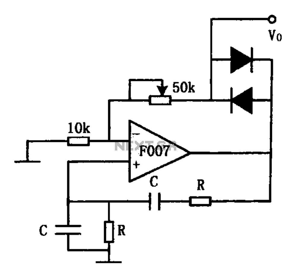
The stable sine wave oscillator circuit is designed to maintain consistent oscillation. The loop gain must be carefully managed; if the gain is excessive, waveform distortion occurs, while insufficient gain can lead to cessation of oscillation. This circuit employs...
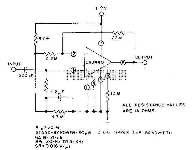
This circuit utilizes the low power leakage, high input impedance, frequency response, and capacitance characteristics of the CA3440 operational amplifier. Only one input coupling capacitor of 500 pF is required to attain a -3 dB low frequency response at...