
Continuity Checker

The circuit utilizes an operational amplifier (U1) configured as a comparator to detect continuity between test probes. The non-inverting input of U1 is set to half of the supply voltage through resistors R1 and R2, establishing a reference level. The inverting input is connected to a voltage divider made up of resistors R3, R4, and R7. The value of R7 is crucial as it is adjusted to ensure that when the test probes are shorted, the voltage at the inverting input remains lower than that at the non-inverting input.
In the scenario where the probes are shorted, the comparator output from U1 transitions to a high state. This high output activates Q1, which functions as a relaxation oscillator. The oscillation generated by Q1 is then coupled to a high-impedance loudspeaker, enabling the production of an audible tone, indicating continuity.
Conversely, when the probes are open, the non-inverting input of U1 is pulled down to the negative supply rail through R2. This condition results in the output of U1 dropping to a low state, effectively disabling Q1 and halting the oscillation. The design ensures that the circuit reliably indicates continuity and provides an audible signal when a connection is made, while remaining inactive when the probes are separated. This operational amplifier-based comparator circuit is a straightforward yet effective solution for continuity testing in various electronic applications. Ul is an op amp used as a comparator. When the test probes are shorted together, resistors R1 and R2 bias the noninverti ng input to half the supply voltage. The inverting input is biased by a voltage divider that consists of R3, R7, and R4. Resistor R7 is adjusted so that the voltage to the inverting input is lower than that to the noninverting input when the probes are shorted together. With continuity across the probes, Ul"s output goes high and supplies power to Ql, which is configured as a relaxation oscillator.
The output of Ql is fed to a high-impedance loudspeaker for an audio tone. When the probe is open, the noninverting input goes to the negative supply rail via R2. This action forces Ul"s output low, which results in no output from the oscillator.
Related Circuits
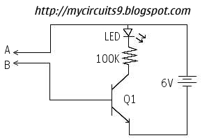
This simple circuit has helped me out on many occasions. It is able to check transistors, in the circuit, down to 40 ohms across the collector-base or base-emitter junctions. It can also check the output power transistors on amplifier...
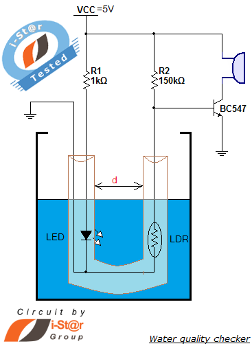
How to measure water purity and test water quality using a simple electronics project. Water purity measurement and water quality analysis can be performed using a water purity checker circuit. This circuit is constructed around a Light Dependent Resistor...
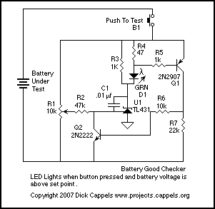
The Battery Good checker. When the button is pressed, the green LED will glow if the battery voltage is above the preset threshold. This version has a higher parts count than the Battery Low version, but a bonus is...
This circuit offers an advantage over traditional continuity testing devices, which typically utilize a multimeter to assess circuit continuity. Multimeters are not suitable for testing high impedance or resistance circuits, such as transformers, capacitors, and high-value resistors. This circuit...

At the time, there was a desire to construct an ultimate continuity tester, leading to the creation of a wish list of required features. A genuine continuity tester is needed, as many multimeters and sounders react to resistances as...
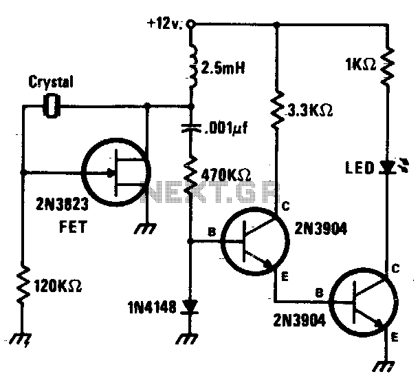
This circuit is a simple Pierce oscillator with an LED go/no-go display. The checker works best with crystals having fundamental frequencies in the seven to eight megahertz range. The Pierce oscillator circuit is a popular choice for generating high-frequency signals,...