
Controlling of Stepper Motor rotation in both direction using 8051 Microcontroller

Stepper motors operate based on the principle of electromagnetic induction. The rotor, which is a permanent magnet, aligns itself with the magnetic field generated by the stator's electromagnets. The stator typically consists of multiple coils arranged in a specific sequence. When voltage is applied to these coils in a precise order, the magnetic field produced causes the rotor to step from one position to another, allowing for controlled movement.
The stepper motor's movement is characterized by discrete steps, which are defined by the number of poles in the rotor and the arrangement of the stator coils. The total number of steps per revolution can vary, with common configurations offering 200 steps per revolution (1.8 degrees per step) or 400 steps per revolution (0.9 degrees per step). This capability enables stepper motors to achieve high precision in positioning applications.
Control of a stepper motor is typically achieved through a driver circuit that sequences the voltage applied to the stator coils. The driver can be controlled using various methods, such as full-step, half-step, or microstepping techniques. Full-step operation energizes two coils at a time, while half-stepping alternates between energizing one and two coils, effectively doubling the resolution. Microstepping further divides each step into smaller increments, allowing for smoother motion and finer control.
In practical applications, stepper motors are widely used in robotics, CNC machinery, and 3D printers due to their ability to provide precise control of position and speed without the need for feedback systems. The simplicity of their control mechanisms and their robustness in various environments make them a popular choice for applications requiring accurate and repeatable motion.Stepper motors consist of a permanent magnet rotating shaft, called the rotor, and electromagnets on the stationary portion that surrounds the motor, called the stator. illustrates one complete rotation of a stepper motor. At position 1, we can see that the rotor is beginning at the upper electromagnet, which is currently active (has voltage applied.
🔗 External reference
Related Circuits
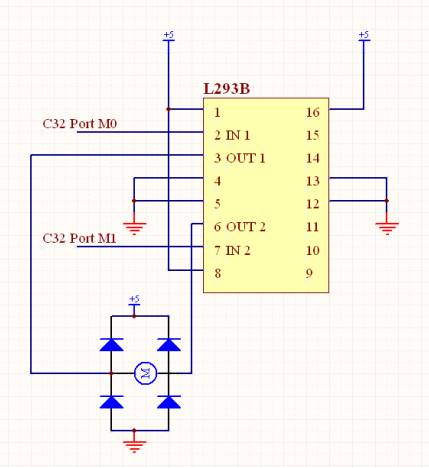
The measured resistance of the door lock motor was approximately 2 ohms. Consequently, when supplied with 5V, the current is calculated as 5V/2Ω = 2.5A. Considering that the peak output current of the L293B is 2A, the current flowing...

This circuit for an intercom is a stand-alone electronic communications system designed for limited or private dialogue. The schematic illustrates the application circuit of the LM390 in the intercom configuration. Gain control can be achieved by capacitively coupling a...
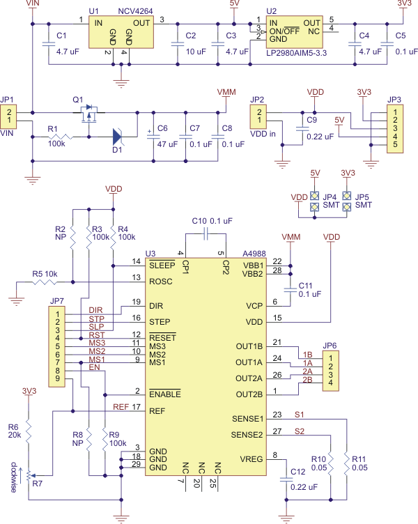
Best 1183 - A4988 Stepper Motor Driver Carrier with Voltage Regulator in Robot Italy. The A4988 stepper motor driver carrier with voltage regulators is a breakout board for Allegro's easy-to-use A4988 microstepping bipolar stepper motor driver. The board has...
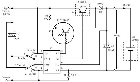
Lithium-ion charger circuit design electronic project using LM3632 controller. The lithium-ion charger circuit utilizing the LM3632 controller is designed to efficiently charge lithium-ion batteries while ensuring safety and longevity. The LM3632 is a highly integrated, step-down linear charger specifically tailored...
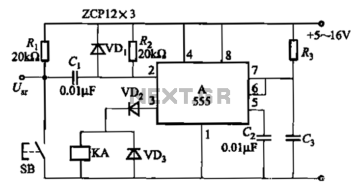
The 555 integrated circuit is utilized in a delay circuit configuration, functioning as a one-shot timer. The delay time can be adjusted using resistor R3 and capacitor C3. Typical values for R3 range from 1 kΩ to 10 MΩ,...
This document presents a simple smoke sensing alarm circuit utilizing a 555 timer. The circuit is designed to detect smoke and trigger an alarm when the air is contaminated. The components employed in this design include an astable multivibrator...