
Courtesy Light Extender
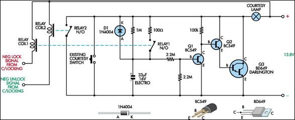
The circuit employs a combination of capacitors, resistors, and transistors to manage the operation of the courtesy light effectively. The 33 µF capacitor plays a critical role in timing the light duration and controlling the fade-out effect. The use of diode D1 prevents backflow of current, ensuring that the discharge path is well-defined when the door is opened. The transistors Q1, Q2, and Q3 are configured in a manner that allows for both the activation and gradual deactivation of the courtesy light, enhancing user experience by providing adequate illumination when entering or exiting the vehicle.
The relay system adds a layer of safety, ensuring that the courtesy light function does not interfere with the car's alarm system. By isolating the circuit from the central locking mechanism, potential issues such as inadvertent activation or failure of the alarm system are mitigated. The 1 MΩ resistor serves to limit the charging current of the capacitor, allowing for a controlled rise in voltage that dictates the timing of the light's fade-out. Overall, this circuit design provides a practical solution for extending courtesy light functionality while maintaining compatibility with existing vehicle security systems.In essence, this circuit is a 15 to 20-second courtesy light extender for cars. It is activated in the usual way by opening a door but it also samples the negative lock/unlock signals from a car alarm or central locking and does two more things. First, when an unlock signal is received, it turns on the courtesy light for 15-20 seconds before you o
pen the door. Second, when a lock signal is received, it turns off the courtesy light immediately, with no fade-out. This is done to eliminate false triggering of the burglar alarm through current drain sensing. When a car door is open or the unlock relay is activated, the 33 µF capacitor discharges through diode D1 and this keeps transistor Q1 turned off.
This allows Q2 and Q3 to turn on and the courtesy lamp is activated. When the door is closed, the courtesy lamps stay illuminated and the 33 µF electrolytic capacitor starts charging through the associated 1MO resistor. As the voltages rises, Q1 turns on slowly, turning off Q2 and Q3 which gradually fades out the courtesy lamp.
If a lock signal from the central locking system is received, relay 1 closes and charges the capacitor instantly, so the lamp turns off immediately. Relays were used to interface to the central locking/alarm system as a safety feature, to provide isolation in case something goes wrong.
🔗 External reference
Related Circuits
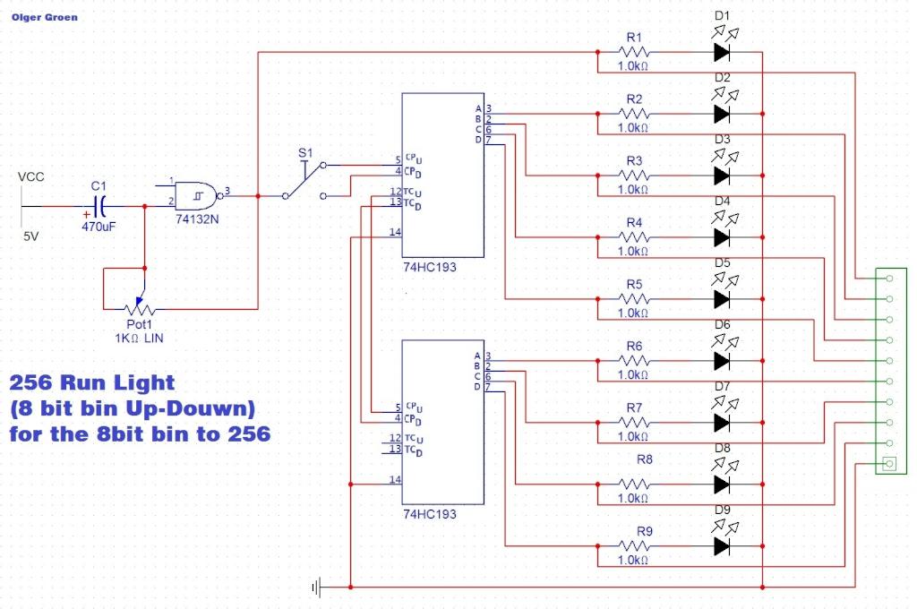
Switch S1 allows for direction change (Up/Down), Pot1 adjusts the clock speed, and LED D1 serves as an indicator for the clock speed. The circuit utilizes a switch (S1) to control the direction of operation, allowing for two modes: upward...
The following circuit illustrates the use of the AD8531 integrated circuit for the automatic control of LCD panel backlighting. Features include the ability to compensate for aging effects. The AD8531 is a precision operational amplifier that is well-suited for applications...
This project involves outdoor LED solar garden lights, which function as an automatic garden lighting system utilizing a light-dependent resistor (LDR) and a 6V/5W solar panel. During daylight hours, the internal rechargeable 6 Volt sealed lead-acid (SLA) battery is...

If R, the sensor matching resistor, is equal to the "dark" resistance of the cadmium sulfide cell, the amplifier output will range from 0 to 2 as the light level varies from "dark" to "bright." The circuit operates similarly,...
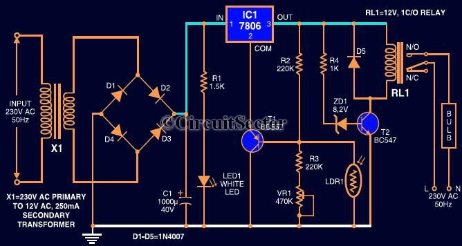
This circuit automates the control of street or porch lights. The automatic lamp controller circuit utilizes a 7806 voltage regulator IC, which can be employed to automate street lights, tube lights, or any other home electrical lighting systems. The...
This is a single-cell LED flashlight circuit. This circuit utilizes a white LED that achieves optimal power efficiency at approximately 20 mA and requires about 3.3 V. The single-cell LED flashlight circuit is designed to provide efficient illumination using a...