
Crystal oscillator-doubler

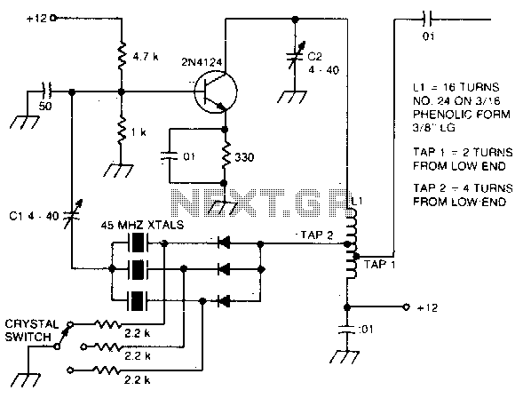
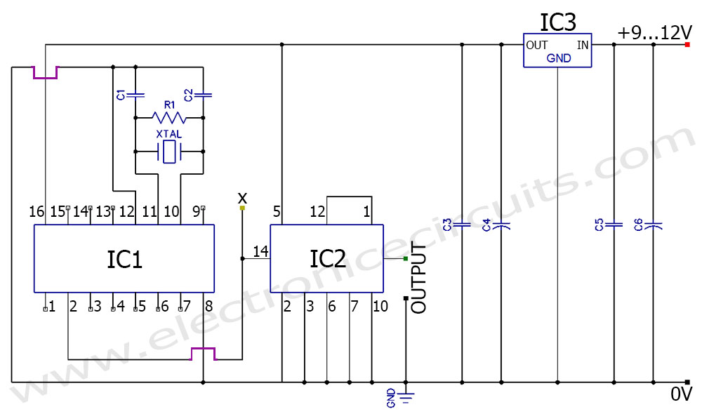
The described circuit utilizes a crystal oscillator configuration that achieves series resonance by balancing the reactance of the crystal with the inductance and capacitance provided by components L1, C1, and C2. The primary role of L1 is to provide inductive reactance, while C1 and C2 serve to create a capacitive reactance that offsets the inductive reactance of L1, achieving resonance at a specific frequency where the total reactance is zero. This is critical for maintaining stable oscillation and ensuring that the output frequency remains consistent.
Capacitor C1 is particularly important, as it allows for fine-tuning of the center frequency of the oscillator. This tuning capability is essential in applications where precise frequency control is required, such as in communication systems or signal processing applications.
In addition to the primary oscillator function, the circuit includes a tank circuit formed by L2 and C3, which serves a dual purpose. Primarily, this tank circuit acts as a frequency doubler, effectively generating an output frequency that is twice that of the input frequency. This is achieved through the resonance of L2 and C3, which is tuned to resonate at the doubled frequency, allowing for efficient energy transfer and amplification of the signal.
The overall architecture of this circuit exemplifies a versatile design suitable for applications requiring frequency modulation and signal doubling, making it a valuable component in advanced electronic systems. Proper selection of L1, L2, C1, and C3 values is crucial to optimize performance and achieve the desired output characteristics.The crystal operates into a complex load at series resonance. Ll, Cl, and C2 balance the crystal at zero reactance. Capacitor Cl fine-tunes the center frequency Tank circuit L2, C3 doubles the output frequency the circuit operates as an FM oscillator-doubler.
Related Circuits
The large inductive phase shift of LI is compensated for by Cl. Overtone crystals have very narrow bandwidth; therefore, the trimmer has a smaller effect than for fundamental-mode operation. The statement discusses the compensation of inductive phase shifts in a...
This bugg is based on my previous 3-transistor transmitter. This bugg unit has many advantages. The transmitter uses a crystal 46.515MHz to hold a steady frequency. The frequency can be fine-tuned by some 100kHz. The transmitter can send data...
Inquiries about selecting the L, C, and R values to achieve a desired frequency are common. It is essential to understand the relationship between these components and the frequency they produce. The desired frequency can be calculated using the...
A highly beneficial project involving a crystal tester circuit, also known as an xtal tester circuit, constructed with only a few components. The circuit forms an oscillator that will only oscillate if the crystal under test is functioning properly....

Can anyone provide guidance on a simple, usable circuit that can be constructed for testing crystals? Numerous circuits have been encountered during online searches. A simple crystal testing circuit can be designed using a few essential components, typically including a...
A frequency generator circuit capable of producing 50 Hz and 60 Hz outputs using a crystal oscillator. This oscillator can be utilized to generate precise frequency signals. This frequency generator circuit employs a crystal oscillator as its core component, which...