
Logic Probe with 74LS47
The Logic Probe circuit serves as an essential diagnostic tool for testing and analyzing TTL (Transistor-Transistor Logic) circuits. It operates by providing a visual indication of the logic state present at a specific node within the circuit. The circuit requires a power supply that matches the voltage levels of the target TTL circuit, typically denoted as Vcc for the positive supply and GND for the ground reference.
The probe is equipped with a "Test" wire that must be connected to the node being tested. The logic levels are defined as follows: a "Low" state is indicated when the voltage at the node is between 0V and 2V, resulting in the illumination of a green LED and the display of a "zero" (0). A "High" state occurs when the voltage is between 3V and 5V, activating a red LED and displaying a "one" (1). The "Impedance" state is characterized by the absence of a connection or a voltage reading between 2V and 3V, during which neither LED is illuminated, indicating that the node is in a high-impedance state.
The circuit design typically incorporates a comparator or a microcontroller to interpret the voltage levels and control the LEDs accordingly. Resistors may be used to limit current to the LEDs, ensuring they operate within safe parameters. The Logic Probe is an invaluable tool for engineers and technicians, facilitating quick and effective troubleshooting of digital circuits by providing immediate visual feedback on the logic states present at various nodes.This circuit is a Logic Probe. It indicates the logic state of the node of any TTL logic circuit. To do that, we have to supply the probe with the same power of the circuit that we want to analyse: same Vcc and same GND. To check the logic level, we must connect the "Test" wire of the probe to the desired node of the circuit that we want to check.
If the level is Low, the probe will display a "zero" (0) and only the green LED will be lighted. If the level is High, the probe will display a "one" (1) and only the red LED will be lighted. If the level is Impedance, the probe will display a nothing and no LED will be lighted. The logic level is "Low" when the "Test" wire is connected to the ground of the circuit (the voltage is between 0V and 2V). The logic level is "Impedance" when the "Test" wire is unconnected (it has no voltage or the voltage is between 2V and 3V).
The logic level is "High" when the "Test" wire is connected to the positive supply of the circuit (the voltage is between 3V and 5V). 🔗 External reference
Related Circuits
When testing circuits with a logic probe, it is sometimes difficult to watch the LEDs on the probe to determine the logic state. With this probe, the logic states are audible. This probe is designed for TTL circuits only...
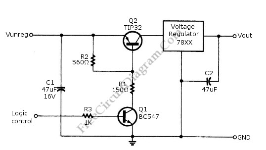
Logic power control of an analog regulator can be useful in applications where a digital circuit or controller needs to manage a power source, such as in EEPROM programmers or other power control systems. This circuit provides ON-OFF control...
NI Multisim software provides advanced virtual instruments and analysis tools that enhance the understanding of circuit designs. One such tool, the measurement probe, acts as a functional interface for observing circuit characteristics and customizing the simulation process within Multisim....
Filter regulators, solenoid valves, quick exhaust valves, flowline pilots - Welcome to Bifold Fluidpower Ltd. Bifold Fluidpower Ltd. specializes in a range of fluid power components that include filter regulators, solenoid valves, quick exhaust valves, and flowline pilots. Each of...
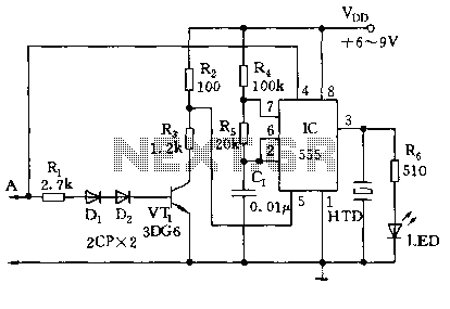
The circuit utilizes a 555 timer along with resistors R4, R5, and capacitor C1 configured in a controllable multivibrator mode. This setup forces the reset terminal (pin 4) to a specific state, allowing for control of the external logic...
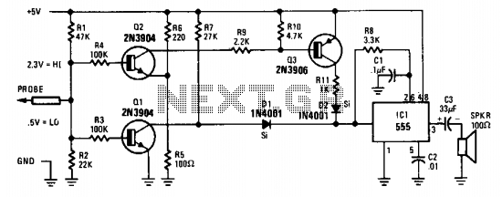
The probe's input circuit detects the signal condition and generates a low-pitched tone for low-level signals (below 0.8 V) or a high-pitched tone for high-level signals (above 2 V). The tone probe employs sound to indicate the status of...