
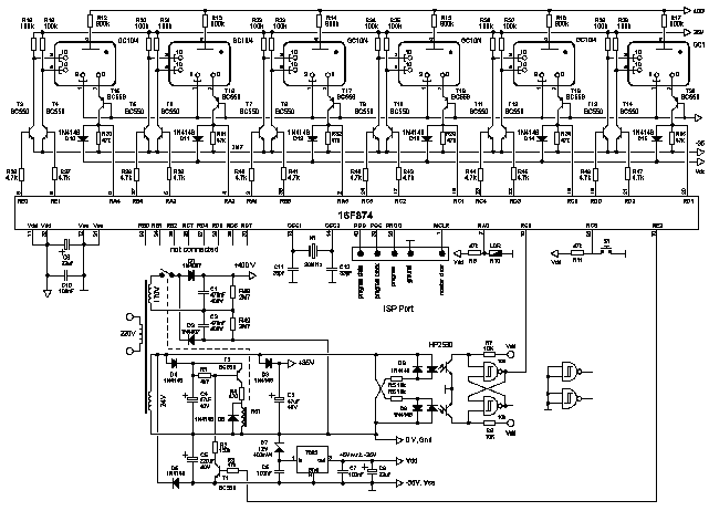
Door Bell Chime Project

The circuit design for the doorbell chime utilizes the versatile 555 timer IC, configured in astable mode to generate an audible tone when the pushbutton switch is activated. The 555 timer serves as an oscillator, producing a square wave output that drives the connected speaker.
The schematic includes five resistors which are strategically placed to set the timing characteristics of the 555 timer. These resistors work in conjunction with the four electrolytic capacitors to determine the frequency and duty cycle of the output waveform. The ceramic capacitor is used for stability and noise filtering, ensuring a clean signal is delivered to the speaker.
Three diodes are incorporated into the design to protect the circuit from reverse polarity and to manage the flow of current, particularly when the pushbutton is engaged. The pushbutton switch acts as the user interface, allowing for manual activation of the chime. When pressed, it completes the circuit, triggering the 555 timer and producing sound through the speaker.
The power supply for the entire circuit is provided by a 9V battery, which ensures adequate voltage for the operation of the 555 timer and the speaker. This simple yet effective design allows for customization, such as adjusting the tone or volume by modifying component values, making it an ideal project for electronics enthusiasts.Build Your Own Door Bell Chime using 555 timer integrated circuit, a speaker, 5 resistors, 4 electrolytic capacitors, 1 ceramic capacitor, 3 diodes, 1 pushbutton switch and 9 V battery as power supply.. 🔗 External reference
Related Circuits
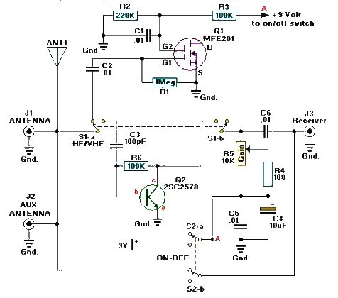
A simple and efficient active antenna electronic project can be designed using this electronic schematic circuit based on transistors. This active antenna project is effective for a wide range of RF frequencies, covering three RF bands: HF, VHF, and...
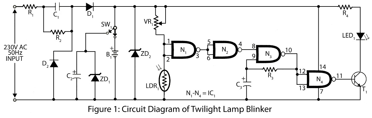
Twilight Lamp Blinker circuit can be constructed using a Light Dependent Resistor (LDR) and a single integrated circuit (IC). The circuit diagram includes a parts list for various projects utilizing the LDR and additional components. The Twilight Lamp Blinker circuit operates...
Electronic devices require precision. When a task is performed multiple times, the outcome is consistently the same. However, there are instances where random results are desirable, such as in gaming applications. This project demonstrates how to create a lottery...
This Dummy Alarm project causes an LED to flash briefly every 5 seconds, simulating the indicator light of a real alarm. The circuit is designed to consume minimal current to extend battery life, allowing it to remain powered continuously....
Instead of simply incrementing the time every new second, it would be beneficial to have a display of forward- and backward-spinning digits, gradually rolling out to the new time, similar to the reels of a slot machine. Decatrons are...
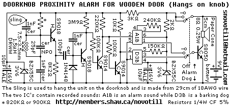
Reverse engineered circuit diagram of a popular retail doorknob alarm. It contains a small transmitter and the doorknob acts as an antenna so it will not work on a metal door. When a person comes close to the doorknob...