
Flashing LED unit
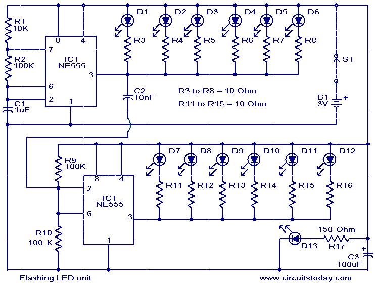
This LED flasher circuit utilizes two CMOS NE555 timers to create a visually appealing rotating LED effect. The first NE555 timer (IC1) is configured as an astable multivibrator, generating a square wave output at a frequency of 4Hz. This output is responsible for driving the first set of LEDs (D1 to D6), which are arranged in a manner that enhances the rotating effect. The duty cycle of 50% ensures that the LEDs are turned on and off equally, contributing to a balanced illumination pattern.
The second NE555 timer (IC2) serves as a trigger pulse inverter, which modifies the output signal from IC1 to control the second set of LEDs (D7 to D12). This configuration allows for a more complex flashing pattern, further enhancing the visual effect. The use of the CMOS variant of the NE555 is advantageous due to its low power consumption, making it suitable for operation with small power sources, such as 3V button cells.
The design choice to use sinking mode for the NE555 timers at low voltages is critical for optimal performance. In this mode, the timers pull the current through the LEDs to ground rather than supplying it, which can lead to improved reliability and brightness at lower voltages. This is particularly important in battery-operated applications where efficiency is paramount.
Finally, LED D13 is incorporated into the circuit as a constant indicator, remaining permanently lit to provide a visual reference of the circuit’s operational state. This design not only serves aesthetic purposes but also enhances user awareness of the circuit's functionality. Overall, the circuit exemplifies effective use of simple components to create engaging visual effects while maintaining low power requirements.The circuit given here is designed as an LED flasher which produces a rotating effect when the LEDs are arranged properly. The circuit has very low current consumption and can be operated from even 3V button cells. The IC 1 (CMOS NE555) is wired as an astable multivibrator wired at a duty cycle of 50% and 4Hz frequency and drives LEDs D1 to D6.
The second IC, IC2 (CMOS NE555) is working as a trigger pulse inverter and drives LEDs D7 to D12. The circuit is arranged such that the ICs sink the current consumed by the LEDs. At low operating voltages like 3V, the CMOS NE 555 performs better when arranged in sinking mode rather than in sourcing mode. The LED D13 remains permanently ON. 🔗 External reference
Related Circuits
An efficient automatic solar garden lights circuit with minimal components. The advantage is that it operates entirely autonomously, with the solar panel functioning as a light detector. It switches the lamp off at dawn, charges the battery during the...
In this circuit, one, two or three neon indicator bulbs can be made to flash in sequence at rates determined by the R and C values. In the single stage circuit, using one lamp, the capacitor charges through the...
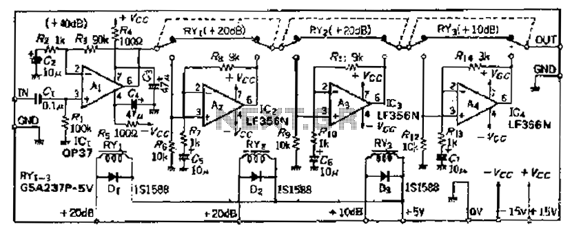
Although the basic amplifier circuit phase AC amplifier remains unchanged, the selection of the correct gain requires the use of series resistors. The circuit does not include a 9kΩ resistor. The input amplifier Ai selected is the OP37, which...
For a transistor to conduct, it requires a voltage of about 0.6 between its base and emitter. This voltage is applied from the wiper of the 47K pot. Now if the pot is at minimum, this voltage is across...
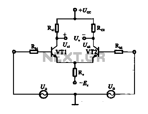
An emitter-coupled differential amplifier circuit is designed to suppress zero drift through circuit symmetry. The effectiveness of zero drift suppression improves with better symmetry; however, in practice, achieving complete symmetry is not feasible. Consequently, the basic differential amplifier circuit...
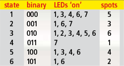
Every DIY enthusiast creates their own electronic dice using LEDs as indicators. This eliminates the need to physically throw the dice; instead, a button press activates the roll. The circuit design ensures fairness by preventing manipulation of the outcome,...
Warning: include(partials/cookie-banner.php): Failed to open stream: Permission denied in /var/www/html/nextgr/view-circuit.php on line 713
Warning: include(): Failed opening 'partials/cookie-banner.php' for inclusion (include_path='.:/usr/share/php') in /var/www/html/nextgr/view-circuit.php on line 713