Full Bathtub Indicator
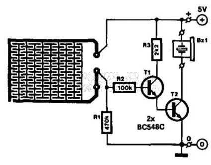
Running a bath can lead to a minor domestic disaster if the taps are forgotten. This indicator activates an audible buzzer when a specific water level is reached. The water sensor and the buzzer driver circuit are integrated on one PC board, allowing the indicator, along with a 9-V battery and buzzer, to be housed in a compact case. The sensor, etched on the PC board, should not be placed in a cast-iron or steel bath; instead, the indicator is secured with a magnet glued to the case. To prevent scratching, the magnet can be covered with plastic or rubber. For polypropylene baths, the indicator can be affixed with blue tack or double-sided adhesive tape. When the water level reaches the sensor, the base of transistor T1 connects to the positive supply line, turning on both T1 and T2 to activate the buzzer B21, a self-oscillating type. The circuit draws approximately 25 mA under these conditions. If steam activates the circuit, sensitivity can be reduced by increasing the value of resistor R2. It is advisable to tin the PC board tracks to prevent corrosion. The transistors used are BC548C, and the buzzer is an active piezo-ceramic resonator.
The described circuit operates as a water level indicator, providing an audible alert when the water reaches a predetermined height. The integration of the water sensor and buzzer driver circuit on a single printed circuit board (PCB) simplifies the design and minimizes the space required for installation.
The water sensor is a critical component, designed to detect the presence of water through conductive properties. It is essential to ensure that the sensor is not placed in conductive materials such as cast iron or steel, as this could lead to inaccurate readings or circuit failure. Instead, a non-conductive mounting method is recommended, such as using a magnet secured to the case, which can be coated with a protective material to avoid damage to the bath surface.
The electronic circuit utilizes two transistors, T1 and T2, both of which are BC548C types. When the water level reaches the sensor, T1 is activated, which in turn activates T2. This action allows current to flow to the buzzer B21, which is a self-oscillating piezo-ceramic resonator. The buzzer emits a sound signal, alerting users to the high water level. The circuit is designed to draw around 25 mA of current when active, ensuring low power consumption while maintaining functionality.
Sensitivity adjustments can be made to the circuit by modifying resistor R2. Increasing its value decreases the circuit's sensitivity to steam, which is particularly useful in environments where steam may inadvertently trigger the buzzer, such as in bathrooms.
To enhance the longevity and reliability of the PCB, it is recommended to tin the tracks to prevent corrosion, ensuring that the electrical connections remain intact over time. This precaution is vital in humid environments where moisture can lead to oxidation and circuit failure.
Overall, this water level indicator circuit provides a practical solution to prevent overflow during bath filling, combining simplicity, effectiveness, and ease of installation in various bath types. Running a bath can end in a minor domestic disaster if you forget to turn off the taps in time. This indicator activ ates an active buzzer to provide an audible warning when a given water level is reached. Because the water sensor and the driver circuit for the buzzer are contained on one PC board, the indicator, together with the 9-V battery and the buzzer, can be built into a compact case. Obviously, the sensor, which is etched on the PC-board, must not be fitted in case-iron or steel bath, the indicator is secured to it with the aid of a magnet glued onto the case.
To prevent scratching the bath, the magnet can be covered in plastic or rubber. If you have a polypropylene bath, the indicator can be stuck to it with blue tack or double-sided adhesive tape. When the water reaches the sensor, the base of T1 is connected to the positive supply line. As a result, T1 and T2 are switched on so that the buzzer B21, a self-oscillating type, is activated.
The current drawn by the circuit in that condition is about 25 mA. In case the circuit is actuated by steam, its sensitivity can be reduced by increasing the value of R2. It is best to tin the PC board tracks to prevent corrosion. T1, T2 = BC548C BZ1 = active piezo-ceramic resonator
