
High-Gain Current Sensor

The circuit operates by leveraging the UA741 operational amplifier, which is configured in a non-inverting or inverting mode to amplify the small voltage drop across the conductor. The voltage drop is proportional to the current flowing through the conductor according to Ohm's law, allowing for accurate current measurement. The gain of the amplifier can be adjusted by modifying the feedback resistor values, thereby allowing for customization based on the specific requirements of the application.
LED1 and LED2 are connected to the output of the amplifier in a manner that indicates the polarity of the current. When the current flows in one direction, one LED will illuminate, while the other will remain off, providing a clear visual indication of the current's direction. This feature is particularly useful in troubleshooting applications where understanding the flow of current is crucial.
The circuit can be effectively used on a PCB to monitor traces for current flow, which is essential in ensuring that the circuit operates within its designed parameters. Additionally, it can help in locating shorts (unintended connections between traces) and opens (disconnections in the circuit), which can lead to circuit failure. By employing this high-gain amplifier configuration, the circuit achieves a high level of sensitivity, making it a valuable tool for engineers and technicians in the field of electronics. A high-gain amplifier using a UA741 is used to sense relative voltage drop in a conductor, and therefore current i n the conductor. i2 can be increased to 10 for increased sensitivity. LED1 and LED2 provide polarity indication. This circuit can be used to detect current flowing in a PC board trace, and also for locating shorts and opens.
Related Circuits
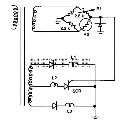
Resistors R1, R2, and the two 2.2 kΩ resistors form a bridge circuit. R2 is a thermistor, and R1 sets the temperature at which L2 lights. Lower or higher temperatures light L1 or L3 to indicate an over- or...
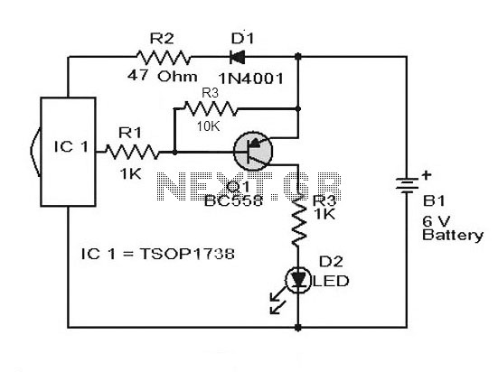
A simple remote control tester circuit with a diagram and schematic using the infrared sensor IC TSOP1738. An LED will blink when infrared waves fall on it, indicating the remote control is functioning. The remote control tester circuit utilizes the...
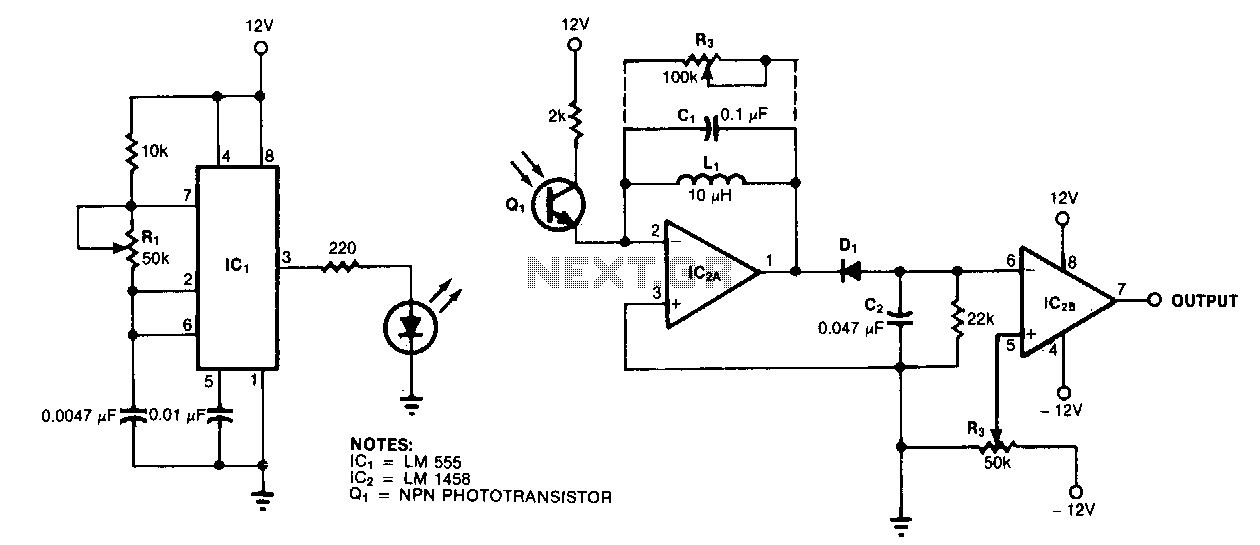
A resonance-tuned narrow-band amplifier enhances the optical object detector's resistance to stray light. The components C1 and L1 within the feedback loop of IC2A enable the operational amplifier to transmit only those frequencies that are at or near the...
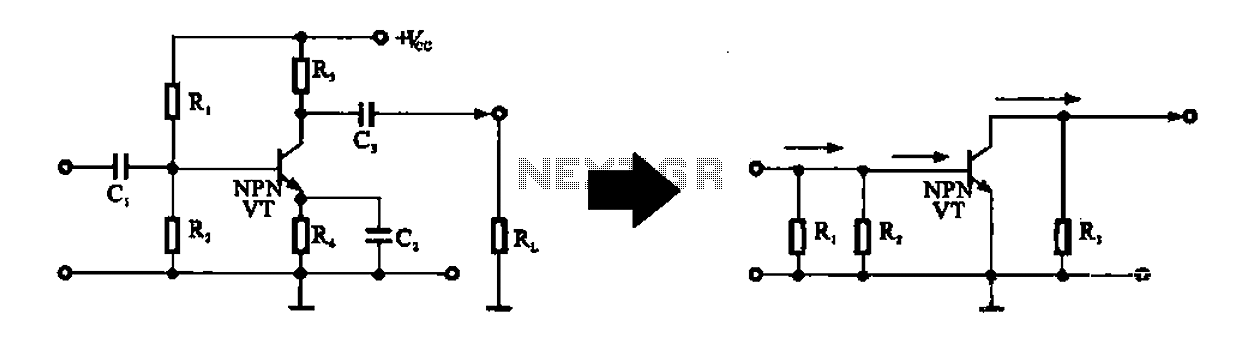
An alternating current voltage amplifier transistor AC path is described. In AC analysis, the internal resistance of the AC supply voltage source is low, which corresponds to a short circuit signal. Consequently, the alternating voltage terminal Vcc is considered...
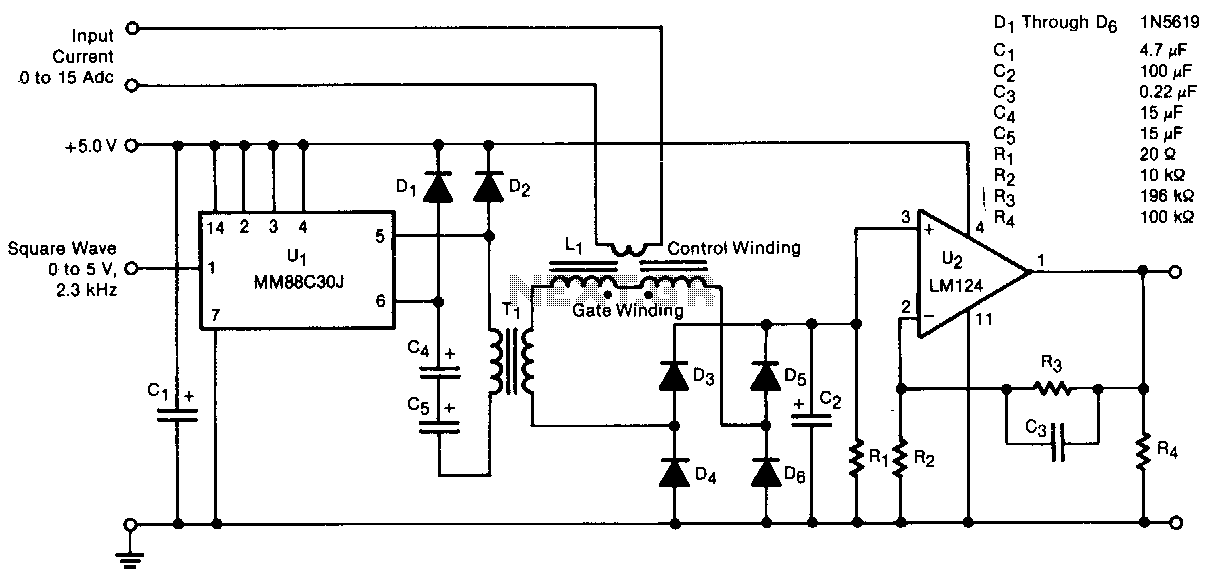
A transducer senses direct current magnetically, providing isolation between the input and the output. The detecting and isolating element is a saturable reactor, through which the input current to be measured passes via a one-turn control coil. The transducer...
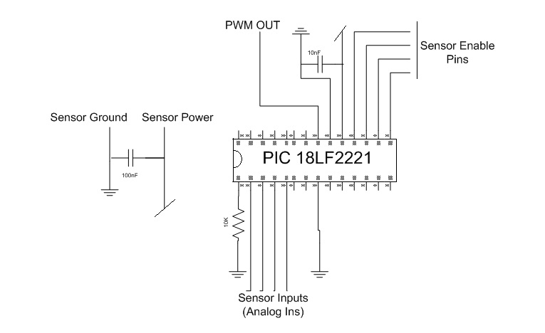
This project was completed during a robotics course taught by Prof. Dave Barret at Olin College. The final project aimed to navigate a maze using a Surveyor robotic platform. Additional sensors were incorporated into the robot, with a focus...