
how to build simple am transmitter

This AM transmitter circuit is characterized by its straightforward design, making it accessible for hobbyists and beginners in electronics. The use of a readily available RF choke simplifies the construction process, as it eliminates the complexities associated with winding an inductor. The fixed capacitors serve to stabilize the circuit size, which is particularly beneficial in portable applications.
The tuning mechanism is user-friendly; the two 220pF capacitors allow for flexible frequency adjustments. By modifying the capacitance, users can easily shift the transmitter's operational frequency to match the desired AM band. This adaptability is crucial for ensuring compliance with local frequency regulations and optimizing performance.
The biasing of the transistor Q1 with a 1MΩ resistor contributes to the overall functionality of the transmitter. The high input impedance enhances the circuit's ability to interface with low-output devices, such as crystal earpieces, which serve as microphones. This choice not only reduces costs but also simplifies the audio input stage, making the circuit more efficient.
In summary, this AM transmitter circuit stands out due to its ease of assembly, compact design, and effective tuning capabilities. It is an excellent choice for educational projects, experimentation, and practical applications in radio transmission.There are not many AM transmitters that are easier to build than this one because the inductor is not tapped and has a single winding. There is no need to wind the inductor as it is a readily available RF choke (eg, Jaycar Cat LF-1536).
To make the circuit as small as possible, the conventional tuning capacitor has been dispensed with and fixed 22 0pF capacitors used instead. To tune it to a particular frequency, reduce one or both of the 220pF capacitors to raise the frequency or add capacitance in parallel to lower the frequency. Q1 is biased with a 1MO resistor to give a high input impedance and this allows the use of a crystal ear piece as a low cost microphone.
🔗 External reference
Related Circuits

The output of pin 5 on the UM3511 integrated circuit can be connected to drive a transistor, which will emit loud sounds through speakers directly. The variable resistor (VR1) determines the frequency of the oscillator circuit and should be...

This circuit utilizes the widely available LM3914 integrated circuit (IC). The IC is straightforward to operate, does not require external voltage regulators due to its built-in voltage regulation feature, and can be powered from nearly any voltage source. The LM3914...
The wireless transmitter circuit utilizes transistor T1 (BF494) as a low-power variable-frequency VHF oscillator. A varicap diode circuit is incorporated to modify the frequency of the FM transmitter and to facilitate frequency modulation using audio signals. The output power...

To simulate this circuit, NI Multisim produced by National Instruments is required. The oscillator will generate a stable waveform. If a file needs to be saved, navigate to the source code. It is important to use Multisim version 11....
This project will explain the function of a simple RF field meter. The unit will be in great help to tune transmitters for best performances. At the bottom left corner you will see a voltage divider. This divider is...
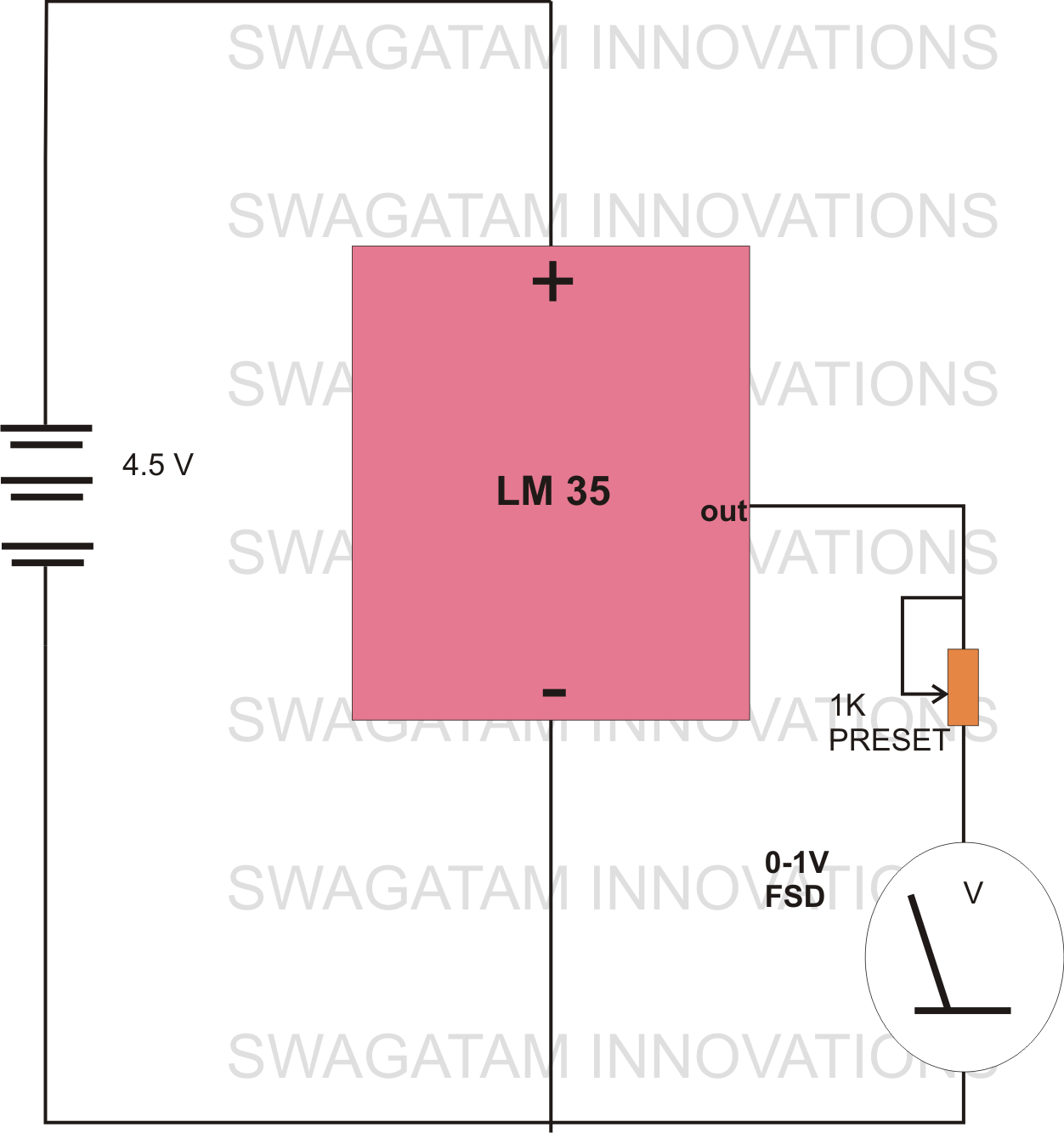
The circuit diagram provided illustrates a straightforward setup. There is no requirement for complex circuitry; simply connect a 0-1 V full-scale deflection (FSD) moving coil meter across the designated pins of the integrated circuit (IC). Adjust the potentiometer as...