
Infa-red Remote Control

The infrared remote control circuit comprises several key components that work together to transmit and receive signals effectively. The primary component of the transmitter is the infrared LED, which emits infrared light modulated at a specific frequency to represent the desired tone. This modulation can be achieved using a simple oscillator circuit, which generates a square wave signal that drives the LED.
The oscillator circuit typically consists of a 555 timer IC configured in astable mode. Resistors and capacitors are selected to set the frequency of oscillation, which corresponds to the tone that the receiver will detect. The output from the 555 timer is connected to the anode of the infrared LED, while the cathode is grounded. A current-limiting resistor is also included in series with the LED to prevent excessive current flow, which could damage the LED.
On the receiving end, the infrared signals are detected by a photodiode or a phototransistor, which is sensitive to the frequency of the transmitted tone. When the phototransistor receives the modulated infrared light, it conducts, allowing current to flow through to the output stage. The output can be connected to a microcontroller or a relay, which can be used to control other devices based on the received signal.
To ensure reliable operation, the receiver circuit may incorporate a bandpass filter that allows only the specific frequency of the transmitted tone to pass through, rejecting other ambient light interference. This filter can be implemented using passive components such as capacitors and inductors or active components like operational amplifiers.
Overall, this infrared remote control system offers a robust solution for wireless communication, minimizing the chances of unintended activations through its tone-based encoding and decoding mechanism.I have received a number of emails requesting schematics for infa-red remotes. So here is one. This remote transmits a tone using an infa-red LED. This tone is decoded by the receiver. Since the receiver only switches when it "hears" the tone, there are no accidental activations. 🔗 External reference
Related Circuits

This single-cable system transmits composite video (NTSC, PAL, or SECAM), power, and channel selection signals. The interface end of the circuit delivers 10 V down the cable, pulses the supply voltage to transmit channel-change commands, and buffers the received...
Various techniques demonstrate how enhanced PWM (pulse-width modulation) intensity control can be utilized in LED (light-emitting diode) drivers. PWM intensity control is a widely adopted method in LED driver circuits to regulate brightness levels. This technique involves modulating the width...
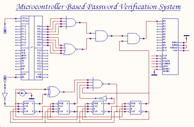
An 8-bit password serves as the input to this system. The password entered by the user is compared with the actual password, which is set in the microcontroller through a microprogram. The outcome of this comparison process generates an...
I have had this project hanging around for ages and have tried to submit it for publication without much enthusiasm so I will make everything available here for the individual constructor. The complete Pascal source code for the compiler...

A prerequisite for this article is that the GCC AVR programming environment is installed as described in the article "Programming the AVR microcontroller with GCC, libc 1.0.4." To avoid installation issues, using the AVR programming CD is recommended. When...
PID-Control with 68HC11. STEPPER CONTROL. 68HC11 read encoder. High accuracy RPM-measurement with 68HC11. The encoder is connected to PORTA PA0 and PA1. The board must be in BOOTSTRAP MODE (tested with Loggyboard). The circuit utilizes a 68HC11 microcontroller for implementing...