
Infrared Remote Control

The infrared remote-controlled switch operates using a 555 timer integrated circuit (IC), which is configured in a monostable mode. This allows the circuit to be triggered by an infrared (IR) signal emitted from a compatible remote control. The primary function of the switch is to control an electrical load, such as a lamp or a fan, remotely.
The circuit consists of several key components: the 555 timer IC, an IR receiver module, a transistor, a relay, and associated passive components like resistors and capacitors. The IR receiver module detects the IR signals from the remote control and converts them into an electrical signal. This signal is fed into the trigger pin of the 555 timer.
When the 555 timer is triggered, it generates a high output signal for a predetermined duration, which can be set by adjusting the resistor and capacitor values connected to the timer. The output from the 555 timer is used to drive a transistor, which in turn activates a relay. The relay acts as a switch, controlling the power to the connected load.
The design allows for flexibility in controlling different types of loads, as long as they fall within the relay's specifications. The circuit is suitable for various applications, such as home automation systems, where convenience and remote operation are desired.
In summary, this infrared remote-controlled switch project highlights the integration of a 555 timer IC with an IR receiver to create a simple yet effective remote control mechanism for managing electrical devices.infrared remote controlled switch is second remote controlled project in this website using 555 ic circuit diagram with description of remote controlled switch. 🔗 External reference
Related Circuits

The TPS6420x controller is designed to operate from one to three series-connected cells or from a 3.3 V or 5 V supply obtained from a USB port. At its output, it can produce 3.3 V at 2 A, suitable...
This circuit is designed for precise centigrade temperature measurement. It includes a transmitter section that converts the sensor's output voltage, which is proportional to the measured temperature, into frequency. The output frequency bursts are transmitted through the mains supply...
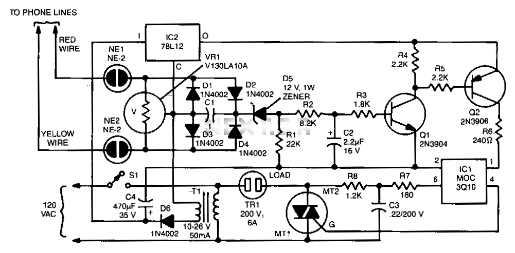
The two neon bulbs will illuminate when the voltage across the ringing circuit exceeds 100 V. These bulbs provide line isolation between the unit and the telephone line. Additionally, they function as a voltage divider for the bridge rectifier...
Here is a circuit for using the printer port of a PC, for control application using software and some interface hardware. The interface circuit along with the given software can be used with the printer port of any PC...

A simple infrared-controlled switch can be operated using a TV remote control. The load can be any AC-powered device connected to the relay. The load activates for three minutes before turning off and can be used to switch on...
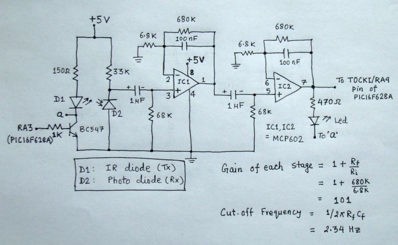
The reflected infrared (IR) signal detected by the photodiode is sent to a signal conditioning circuit, which filters out unwanted signals and amplifies the desired output. The circuit begins with a photodiode that captures the reflected IR signals. The photodiode...