
JTAG from a router

The circuit utilizes a veroboard layout for quick prototyping, emphasizing functionality over aesthetics. The 74HC04 hex inverter is employed to buffer the JTAG signals (TMS, TCK, TDI), ensuring that the output signals maintain integrity when interfacing with the target device. The external Vcc connection allows for flexibility in voltage levels, accommodating various target circuit requirements. The inclusion of zener diodes serves as a protective measure against over-voltage conditions, safeguarding the GPIOs from damage.
The design also reflects considerations for signal integrity and proper interfacing with the AR7 microcontroller. The GpioCtrl class architecture allows for modularity and ease of modification, crucial for adapting to different hardware configurations. The read-modify-write mechanism employed for GPIO manipulation is a common approach in microcontroller interfacing, ensuring that state changes are handled effectively.
The dual Ethernet ports on the AR7 highlight the importance of proper initialization and management of hardware resources in embedded systems. The provided patch demonstrates practical solutions to common problems encountered during development. Overall, this circuit represents a practical approach to JTAG interfacing and GPIO management in embedded applications, showcasing the balance between quick prototyping and functional design.It`s a quick hack on veroboard rather than a neat PCB, but here`s the schematic. Three outputs (TMS, TCK, TDI) run to the 74HC04 for buffering. The /RESET output drives a pull-down NPN transistor directly. Note that the 74HC04 is driven from an external Vcc taken from the target circuit; this allows the output voltage to be controlled by the targe t. Supplying 5V, for example, will let TMS, TCK, etc. have a full 0-5V swing; however inputs to the wrtag will result in the 74HC04 outputs driving the GPIOs at greater than 3. 3V. To protect against this, two zener diodes clamp the Misc and TDO inputs to 3. 3V. Also, they have a 50ohm resistor in series in case the input GPIOs are configured as outputs before cblsrv can reconfigure them as inputs.
Grotty, but it works; it`s not hugely useful and I end up driving the buffer Vcc from the box`s 3. 3V out anyway ” everything I need to JTAG is currently 3. 3V and any lower will require buffering a little more exotic than a 74HC04. Consider using one of TI`s dual-supply level conversion buffers instead. There are two ethernet ports on this version of the AR7. My kernel initialised them in the wrong order, making eth0 the non-functional PHY-less one, which upset OpenWRT a little. There`s a hacky patch below to just disable probing one, so eth0 works. The code to bit-bang the parallel port has been split into a separate class, which drives pins via a new GpioCtrl class.
An implementation of this (in GpioCtrl_ar7. cpp) drives the AR7 GPIOs on the pins listed above. Note that GpioCtrl_ar7. cpp is specific to my wiring ” but the pins are #defined so are easy to change. Note also that their sense is inverted because I`m using an inverter to buffer them! The AR7 GPIOs require a read-modify-write to change a pin state, as there`re no SETPIN/CLEARPIN-type registers. There are also two users of the pins: the kernel with its blinkyLEDs (status, network) infrastructure and cblsrv in userland.
It sounds like locks are required, but none are, really. This is because: The kernel`s read-[AND, OR]-write in gpio_set_value() looks atomic w. r. t. userland in that the kernel will never return having read but not written the pin state. Any state we`re about to write does not get corrupted by being preempted and the kernel flashing an LED. But, the kernel pin state is just flashing LEDs, which is `lossy`. It doesn`t matter if the Ethernet LED blinks 1ms too little, as long as the user application isn`t affected.
If another GPIO function is added (such as driving an LCD) this will have to either be driven from the cblsrv binary or careful locking will have to occur between the two GPIO-using tasks. Great! It`s also faster than I expected for bit-bangy code; even though I`ve made no attempt to optimise the bitbang cblsrv code it downloads bitstreams really quick ” about 130KBytes/sec.
It`s reliable, too, and a nice piece of bench equipment to have around. LCD: There are enough spare GPIOs to drive an HD44780-style character LCD. This would be useful to display the MAC address and IP address obtained from DHCP. It`s more glitter than necessary though, as I just give out a static IP address for the wrtag`s MAC address. OpenOCD: A cable driver backend for OpenOCD that uses the cblsrv protocol over TCP should allow the wrtag to be useful as a general-purpose JTAG debugger/ICE for ARM, etc.
🔗 External reference
Related Circuits
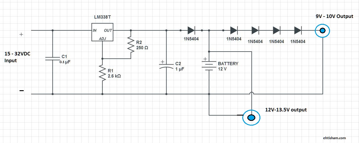
This is a basic solution that functions effectively, allowing for the powering of DSL or Wi-Fi routers for extended periods, as well as any other devices compatible with 9V or 12V. This setup ensures continuous internet access for laptops...
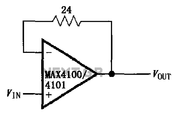
The circuit illustrated is a unit gain buffer circuit utilizing the MAX4100/4101 operational amplifiers. It incorporates a small resistor (24 ohms) within the feedback loop of the amplifier, thereby establishing a unity gain buffer. This configuration maximizes the bandwidth...

This design concept outlines a 12-V DC to 5-V DC (±5%) switched-mode power supply (SMPS). The supply utilizes a 12-V input derived from an array of four 3-V DC, 40-mA solar cells connected in series. The proposed switched-mode power supply...
A couple of motors were salvaged from an old printer, and there is uncertainty regarding how to connect them to a breadboard and subsequently to a Raspberry Pi. A cobbler kit for the Raspberry Pi is available for this...
The following circuit is an example of how to get power from an RS-232 serial port. It provides regulated +5V power for logic circuits and also unregulated positive and negative power supplies for the RS-232 transmitting circuit. The circuit...
This model is very simple and charges as long as you hold the pushbutton: This circuit design features a straightforward pushbutton charging mechanism. The primary components include a power source, a pushbutton switch, a charging circuit, and a load. When...